5.5 Mesh Quality Assessment
Quality Describe {Hex | Hexahedral | Tet | Tetrahedral | Face | Quad | Quadrilateral | Tri | Triangular}
5.5.1 Automatic Mesh Quality Assessment
Cubit performs an automatic calculation of mesh quality which warns users when a particular meshing scheme or other meshing operation has created a mesh whose quality may be inadequate. These warnings are supplied in case the user forgets to manually check the mesh quality.
Cubit automatically calculates the SHEAR quality of hexahedral and quadrilateral elements and the SHAPE quality of tetrahedral and triangular elements. The SHEAR metric measures element skew and ranges between zero and one with a value of zero signifying a non-convex element, and a value of one being a perfect, right-angled element. The SHAPE metric also ranges between zero and one with a value of zero signifying a degenerate or inverted element and a value of one signifying a perfect, equilateral element. The quality of the mesh is then defined to be the minimum value of the shear metric for hexahedral and quadrilateral elements and the shape metric for tetrahedral and triangular elements, with the minimum taken over the elements in the mesh.
Set Quality Threshold <double=0.2>
Set Print Quality { WARNING|Error|Off }
5.5.2 Coincident Node Check
The ability to check for coincident nodes in the model is available in Cubit. It uses an efficient octal hash tree to make the comparisons.
To check for coincident nodes
On the Command Panel, click on Mesh.
Click on Volume, Surface, Curve, Vertex or Group.
Click on the Quality action button.
Select Coincidence Check from the drop-down menu.
Select Coincident Nodes from the Type of Coincidence Check menu.
Enter the appropriate settings.
Click Apply.
Quality Check Coincident Node [ In ] [Group|Body|Volume|Surface|Curve|Vertex <id_range> ] [ Merge [Delete] ] [ HIGHLIGHT|Draw [color <number>]] [List] [Into Group [names|id] ]
If the model being operated on is from an imported universal file (i.e., no geometry exists in the model), you can merge the coincident nodes with the merge option. In this case delete allows you to delete the extra nodes (recommended). If you do not delete them they are placed into an output group.
set Node Coincident Tolerance [<value>]
5.5.3 Controlling Mesh Quality
If the quality of a model after meshing isn’t acceptable, there are two options available to improve that quality. The user can ask for more smoothing, or delete the mesh and start over. There are some commands that the user can invoke before meshing the model which can help to improve mesh quality. Some of them are discussed here.
5.5.3.1 Skew Control
The philosophy behind the skew control algorithm is one of subdividing surfaces into blocky, four-sided areas which can be easily mapped. The goal of this subdivide-and-conquer routine is to lessen the skew that a mesh exhibits on submapped regions. By controlling the skew on these surfaces, the mesh of the underlying volume will also demonstrate less skew.
To control skew or delete skew control
On the Command Panel, click on Mesh and then Surface.
Click on the Control Skew action button.
Select Control Skew or Delete Control Skew from the drop-down menu.
Enter the appropriate value for Surface ID(s). This can also be done using the Pick Widget function.
Click Apply.
Control Skew Surface <surface_id_range> [Individual]
Delete Skew Control Surface {surface_list} [Propagate]
The user also has the ability to delete the changes that the skew control algorithm has made. This is done by using the delete skew control command.
When the user requests the deletion of the skew control changes on a given surface, every curve on that surface will have the skew control changes deleted, even if a given curve is shared with another surface on which skew control was performed. If the user wishes to propagate the deletion of skew control to all surfaces which are affected by one (or more) particular surfaces, the keyword propagate should be used.
5.5.3.2 Propagate Curve Bias
When a bias mesh scheme is applied to a curve, this sometimes creates skewing of the surface mesh that is attached. Sometimes the user will want to ensure that the same bias is applied to curves on attached surfaces so that this skewing is minimized.
To propagate curve bias
On the Command Panel, click on Mesh and then Curve.
Click on the Mesh action button.
Enter the appropriate value for Select Curves. This can also be done using the Pick Widget function.
Select Bias from the first drop-down menu.
Select Propagate Curve Bias from the second drop-down menu.
Select Volume, Surface or Group from the third drop-down menu and enter the appropriate settings.
Click Apply and then Mesh.
Propagate Curve Bias [Surface|Volume|Body|Group <id_list>]
5.5.3.3 Adjust Boundary
To adjust a boundary
On the Command Panel, click on Mesh and then Surface.
Click on the Adjust Boundaries action button.
Enter the appropriate value for Surface ID(s). This can also be done using the Pick Widget function.
Enter the appropriate value for Angle.
Click Apply.
Adjust Boundary {Surface|Group} <id_range> [Angle <double>]
5.5.4 Metrics for Edge Elements
The metrics used for edge elements in Cubit are summarized in the following table:
|
|
|
|
|
|
|
|
5.5.4.1 Quality Metric Definitions:
Length: Distance between beginning and ending nodes of an edge
5.5.4.2 Comments on Algebraic Quality Measures
The quality command for edge length only accepts edge elements as input; it does not accept geometry as input.
The length metric is currently only available for edge elements. Edge elements are created by default when curves and surfaces are meshed. Edge elements are not created for interior volume elements.
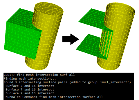
5.5.5 Finding Intersecting Mesh
Find Mesh Intersection {Block|Body|Surface|Volume} <id_list> [with {Block|Body|Surface|Volume} <id_list>] [low <value=0.0001>] [high <value>] [exhaustive] [worst <num_worst>] [draw] [log] [group<’name’>]
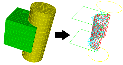
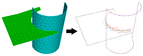
5.5.5.1 Finding Intersecting 2D Mesh
5.5.5.2 Facetted Representation
Detecting mesh intersections between surfaces works entirely off of the mesh, converting the mesh into triangular facets. (The facetted representation is what you see in a shaded view in the graphics). For example, a quad is split into two triangles. Higher order 2D elements are split into multiple triangles.
5.5.5.3 Drawing Mesh Intersection
Draw Surface <id> <id> mesh intersection [add] [include_volume]
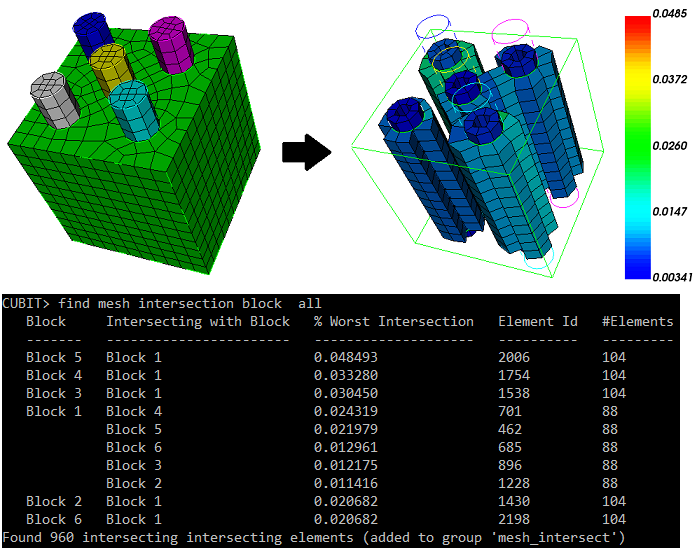
5.5.5.4 Finding Intersecting 3D Mesh
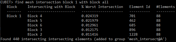
With 3-dimensional entities mesh element intersections can be located by specifying entities: blocks, bodies, or volumes. If intersections are found the intersecting elements are put into a group named ’mesh_intersect’ unless the user has specified another name using the group <’name’> option. Data is printed to the terminal detailing the intersections. The largest intersection value is reported for each pair of intersecting entities (blocks, volumes, or bodies). This value is the fraction of an element’s volume (which element belongs to the entity in the first column) that intersects elements belonging to the entity in the second column. See Figure 364 below. The information printed in columns from left to right is:
the entities that have intersecting mesh
the other entities with which that entity’s mesh intersects
the highest intersection value of an element belonging to the entity in column one
the id of that element
the number of elements of the entity in column one intersecting other elements of the entity in column two
The low and high options set how much cumulative intersection should be detected. A low value of 0.1 would ignore elements that do not intersect more than 10% of their volume. Similarly, a high value of 0.5 would discard elements that intersect more than 50% of their volume. Both low and high can be used simultaneously. The default for the low value is 0.0001
The exhaustive option examines all elements for intersection. The default is to only examine elements with nodes on the boundary of the specified entities, anticipating that the intersections will occur mostly at boundaries.
The worst parameter limits the printout to the ’n’ worst entities with elements of the highest intersections. The intersection fraction reported here is the cumulative intersection an element has with elements of all other entities in the check.
The draw option draws the intersecting elements using a color spectrum, red corresponding to high intersection and green to low. The color is according to cumulative intersection, as described in the worst option.
If the log option is specified, the output from the command will also be sent to a file named "mesh_intersection01.txt", with the number used in the file name incremented as needed. This becomes useful when you have hundreds of volumes with intersections.
Note:
The shape of higher-order mesh elements is considered when computing intersection.
3D mesh intersection detection works on free mesh, as long as it has been placed into blocks.
An intersection fraction greater than 100% is possible, when multiple elements in different entities intersect an element by more than its volume
5.5.6 Metrics for Hexahedral Elements
The metrics used for hexahedral elements in CUBIT are summarized in the following table:
|
|
|
|
|
|
|
|
|
|
|
|
|
|
|
|
|
|
|
|
|
|
|
|
|
|
|
|
|
|
|
|
|
|
|
|
|
|
|
|
|
|
|
|
|
|
|
|
|
|
|
|
|
|
|
|
|
|
|
|
|
|
|
|
|
|
|
|
|
|
|
|
|
|
|
|
|
|
|
|
|
|
|
|
|
|
|
|
|
|
5.5.6.1 Hexahedral Quality Definitions
With a few exceptions, as noted below, Cubit supports quality metric calculations for linear hexahedral elements only. When calculating quality metrics, that only support linear elements, for a higher order hexahedral element, Cubit will only use the corner nodes of the element.
Aspect Ratio: Maximum edge length ratios at hex center.
skew: Maximum |cos A| where A is the angle between edges at hex center.
taper: Maximum ratio of lengths derived from opposite edges.
element volume: Jacobian at hex center.
stretch: Sqrt(3) * minimum edge length / maximum diagonal length.
diagonal ratio: Minimum diagonal length / maximum diagonal length.
dimension: Pronto-specific characteristic length for stable timestep calculation. Char_length = Volume / 2 grad Volume.
condition no. Maximum condition number of the Jacobian matrix at 8 corners.
jacobian: Minimum pointwise volume of local map at 8 corners at center of hex. Cubit also supports Jacobian calculations for hex27 elements.
scaled jacobian: For linear elements the minimum Jacobian divided by the lengths of the 3 edge vectors.
shear: 3/Mean Ratio of Jacobian Skew Matrix
shape: 3/Mean Ratio of weighted Jacobian Matrix
relative size: Min(J, 1/J), where J is the determinant of weighted Jacobian matrix
shear & size: Product of Shear and Size Metrics
shape & size: Product of Shape and Size Metrics
timestep: The approximate maximum timestep that can be used with this element in explicit transient dynamics analysis. This critical timestep is a function of both element geometry and material properties. To compute this metric on hexes, the hexes must be contained in a element block that has a material associated to it, where the material has poisson’s ratio, elastic modulus, and density defined.
distortion: {min(|J|)/actual volume}*parent volume, parent volume = 8 for hex. Cubit also supports Distortion calculations for hex20 elements.
5.5.6.2 References for Hexahedral Quality Measures
FIMESH code
Unknown
P. Knupp, Algebraic Mesh Quality Metrics for Unstructured
Initial Meshes, to appear in Finite Elements for Design
and Analysis.Flanagan, D.P. and Belytschko, T., 1984, "Eigenvalues and Stable Time Steps for the Uniform Hexahedron and Quadrilateral," Journal of Applied Mechanics, Vol. 51, pp.35-40.
SDRC/IDEAS Simulation: Finite Element Modeling - User’s Guide
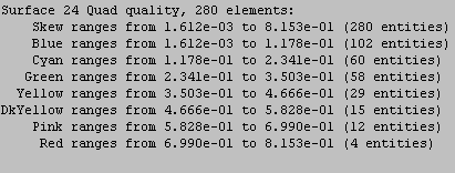
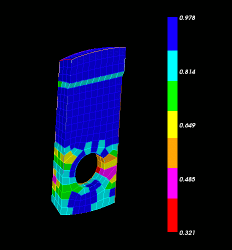
5.5.7 Mesh Quality Example Output
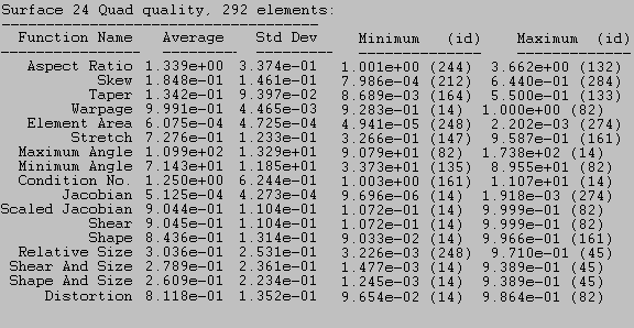
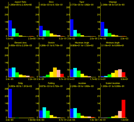
Figure 2. Histogram output from command "Quality Surface 24 Draw Histogram"
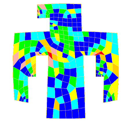
Figure 368: Graphical output of quality metric for command "Quality Surface 24 Skew Draw Mesh"
5.5.8 Mesh Quality Command Syntax
To view the quality of a mesh
On the Command Panel, click on Mesh.
Click on Volume or Surface.
Click on the Quality action button.
Select Quality Metrics from the drop-down menu.
Enter the appropriate value for Volume ID(s) or Surface ID(s). This can also be done using the Pick Widget function.
Specify the Quality Metric type to view from the Quality Metric drop-down menu.
Select Display Graphical Summary.
Click Apply.
Quality {geom_and_mesh_list} [metric name] [quality options] [filter options]
If a specific metric name is given, only that metric or metrics are computed for the specified entities. Note that the metric given must be one which applies to the given entities. To see a list of quality metrics for individual entities see the Mesh Quality Assessment section and select the desired entity type: hexahedral, tetrahedral, quadrilateral, triangle. or edge
The metric name can also be more general than a specific metric. Four generalized options for metric name can be used:
allmetrics: All of the metrics corresponding to the element type of the geom_and_mesh_list will be computed and reported.
algebraic: All algebraic metrics corresponding to the element type of the geom_and_mesh_list will be computed and reported (e.g., Shape, Shear, Relative Size).
robinson: All Robinson metrics corresponding to the element type of the geom_and_mesh_list will be computed and reported (e.g., Aspect Ratio, Skew, Taper).
traditional: All the traditional Cubit metrics corresponding to the element type of the geom_and_mesh_list will be computed and reported (e.g., area, volume, angle, stretch, dimension).
If no metric name is supplied, the default metric is "shape".
5.5.8.1 Quality Options
The quality options are:
[ Global | Individual ]
5.5.8.1.1 Draw
[ Draw [Histogram] [Mesh] [Monochrome] [Add] ]
If monochrome is specified, then the graphics are not color-coded. If add is specified, then the current display is not cleared before drawing the mesh elements.
5.5.8.1.2 List
[ List [Detail] [Id] [Verbose Errors] ] [Geometry]
5.5.8.1.3 Filter
[High <value>] [Low <value>]
[Top <number>] [Bottom <number>]
5.5.9 Metrics for Quadrilateral Elements
The metrics used for quadrilateral elements in Cubit are summarized in the following table:
|
|
|
|
|
|
|
|
|
|
|
|
|
|
|
|
|
|
|
|
|
|
|
|
|
|
|
|
|
|
|
|
|
|
|
|
|
|
|
|
|
|
|
|
|
|
|
|
|
|
|
|
|
|
|
|
|
|
|
|
|
|
|
|
|
|
|
|
|
|
|
|
|
|
|
|
|
|
|
|
|
|
|
|
|
|
|
|
|
|
5.5.9.1 Quadrilateral Quality Definitions
aspect ratio: Maximum edge length ratios at quad center
skew: Maximum |cos A| where A is the angle between edges at quad center
taper: Maximum ratio of lengths derived from opposite edges
warpage: Cosine of Minimum Dihedral Angle formed by Planes Intersecting in Diagonals
element area: Jacobian at quad center
stretch: Sqrt(2) * minimum edge length / maximum diagonal length
minimum angle: Smallest included quad angle (degrees).
maximum angle: Largest included quad angle (degrees).
condition no. Maximum condition number of the Jacobian matrix at 4 corners
jacobian: Minimum pointwise volume of local map at 4 corners & center of quad
scaled jacobian: Minimum Jacobian divided by the lengths of the 2 edge vectors
shear: 2/Condition number of Jacobian Skew matrix
shape: 2/Condition number of weighted Jacobian matrix
relative size: Min( J, 1/J ), where J is determinant of weighted Jacobian matrix
shear and size: Product of Shear and Relative Size
shape and size: Product of Shape and Relative Size
distortion: {min(|J|)/actual area}*parent area, parent area = 4 for quad
5.5.9.2 Comments on Algebraic Quality Measures
Shape, Relative Size, Shape & Size, and Shear are algebraic quality metrics that apply to quadrilateral elements. Cubit encourages the use of these metrics since they have certain nice properties (see reference 5 below). The metrics are referenced to a square-shaped quadrilateral element, thus deviations from a square are measured in various ways.
Shape measures how far skew and aspect ratio in the element deviates from the reference element.
Relative size measures the size of the element vs. the size of reference element. If the element is twice or one-half the size of the reference element, the relative size is one-half. The reference element for the Relative Size metric is a square whose area is determined by the average area of all the quadrilaterals on the surface mesh under assessment
Shape and size metric measures how both the shape and relative size of the element deviate from that of the reference element.
The SHEAR metric is based on the condition number of the skew matrix. SHEAR is really just an algebraic skew metric but, since the word skew is already used in the list of quad quality metrics, Cubit has chosen to use the word ’shear.’
Shear = 1 if and only if quadrilateral is a rectangle.
The Robinson ’skew’ metric equals the ideal (zero) if the quad is a rectangle. It also attains the ideal if the quad is a trapezoid, a kite, or even triangular!
5.5.9.3 References for Quadrilateral Quality Measures
FIMESH code.
Unknown.
P. Knupp, Algebraic Mesh Quality Metrics for Unstructured Initial Meshes, submitted for publication.
6. SDRC/IDEAS Simulation: Finite Element Modeling–User’s Guide
5.5.9.4 Details on Robinson Metrics for Quadrilaterals

5.5.10 Metrics for Tetrahedral Elements
The metrics used for tetrahedral elements in CUBIT are summarized in the following table:
|
|
|
|
|
|
|
|
|
|
|
|
|
|
|
|
|
|
|
|
|
|
|
|
|
|
|
|
|
|
|
|
|
|
|
|
|
|
|
|
|
|
|
|
|
|
|
|
|
|
|
|
|
|
|
|
|
|
|
|
| ||||
|
|
|
| |
|
|
|
|
5.5.10.1 Tetrahedral Quality Definitions
With a few exceptions, as noted below, Cubit supports quality metric calculations for linear tetrahedral elements only. When calculating quality metrics, that only support linear elements, for a higher order tetrahedral element, Cubit will only use the corner nodes of the element.
Aspect Ratio Beta: CR / (3.0 * IR) where CR = circumsphere radius, IR = inscribed sphere radius
Aspect Ratio Gamma: Srms**3 / (8.479670*V) where Srms = sqrt(Sum(Si**2)/6), Si = edge length
Element Volume: (1/6) * Jacobian at corner node
Condition No.: Condition number of the Jacobian matrix at any corner
inradius: For all tets but tetra10s, the radius of the smallest, fully contained sphere of the linear tet. For tetra10s, the mid-edge nodes are used to subdivide the tet into 12 linear sub-tets. The inradius is the smallest inradius of the 12 linear sub-tets * 2.3.
jacobian: Minimum pointwise volume at any corner. Cubit also supports Jacobian calculations for tetra15 elements.
For tetra15 elements, all 15 nodes are included for the Jacobian calculation. For all other tet types, only the corner nodes are considered.
scaled jacobian: For linear elements the minimum Jacobian divided by the lengths of 3 edge vectors
shape: 3/Mean Ratio of weighted Jacobian Matrix
relative size: Min(J, 1/J), where J is the determinant of the weighted Jacobian matrix
shape & size: Product of Shape and Relative Size Metrics
timestep: The approximate maximum timestep that can be used with this element in explicit transient dynamics analysis. This critical time step is a function of both element geometry and material properties. To compute this metric on tets, the tets must be contained in an element block that has a material associated to it, where the material has poisson’s ratio, elastic modulus, and density defined.
5.5.10.1.1 High Order Elements
The preceding metrics will measure quality based only on the 4 corner nodes of the tetrahedron. The following metrics also take into account the mid nodes.
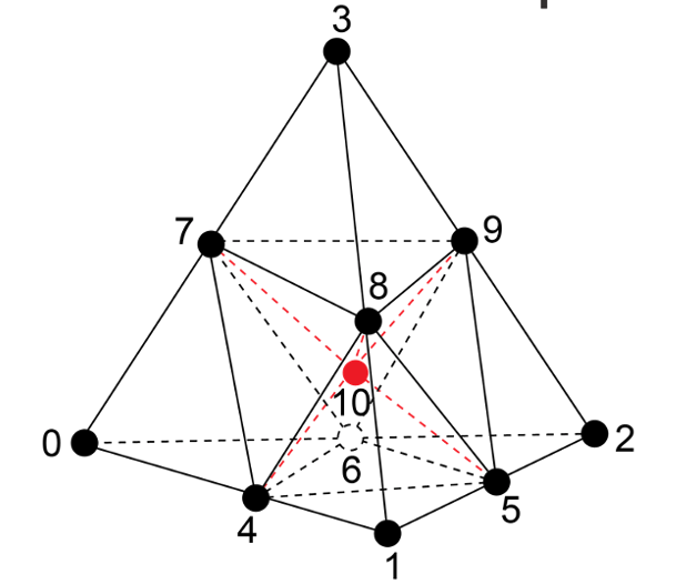
normalized inradius: Ratio of minimum subtet inner radius to tet outer radius (circumsphere). Subtets are defined by subdividing the tet into 12 smaller tets by using a common point at the centroid of the tet and the 6 mid-edge nodes as shown in Figure 371. The minimum in-radius of any of these 12 tets normalized by its parent outer-radius and a constant is used to determine this metric. The Normalized Inradius metric is also valid for linear elements, except that all mid-edge nodes are defined as the midpoint of their corner nodes.
Figure 371: Subtet subdivision used for determining Normalized Inradius quality metric
distortion: {min(|J|)/actual volume}*parent volume, parent volume = 1/6 for tet. Cubit also supports Distortion calculations for tetra10 elements.
For tetra10 elements, the distortion metric can be used in conjunction with the shape metric to determine whether the mid-edge nodes have caused negative Jacobians in the element. The shape metric only considers the linear (parent) element. If a tetra10 has a non-positive shape value then the element has areas of negative Jacobians. However, for elements with a positive shape metric value, if the distortion value is non-positive then the element contains negative Jacobians due to the mid-side node positions.
Note that, for tetrahedral elements, there are several definitions of the term "aspect ratio" used in literature and in software packages. Please be aware that the various definitions will not necessarily give the same or even comparable results.
5.5.10.2 References for Tetrahedral Quality Measures
P. Knupp, Algebraic Mesh Quality Metrics for Unstructured Initial Meshes, to appear in Finite Elements for Design
and Analysis.Flanagan, D.P. and Belytschko, T., 1984, "Eigenvalues and Stable Time Steps for the Uniform Hexahedron and Quadrilateral," Journal of Applied Mechanics, Vol. 51, pp.35-40.
SDRC/IDEAS Simulation: Finite Element Modeling - User’s Guide
5.5.11 Mesh Topology Check
To check mesh entities topology
On the Command Panel, click on Mesh.
Click on Hex, Tet, Quad, Tri or Edge.
Click on the Quality action button.
Select Topology Check from the drop-down menu.
Enter the appropriate value. This can also be done using the Pick Widget function.
Click Apply.
Quality Check Topology [[Hex <range>] [Tet <range>] [Face <range>] [Tri <range>]]
model edges
coincident nodes
coincident quadrilateral(faces) or triangles
Model Edge Check
The model edge check will find edges with adjoining quadrilaterals or triangles whose angles between the surface normals exceed a specified value. The default angle is 40 degrees.
The following commands check for model edges:
To check for model edges on volumes, surfaces and groups
On the Command Panel, click on Mesh.
Click on Volume, Surface or Group.
Click on the Quality action button.
Select Model Edge Check from the drop-down menu.
Enter the appropriate values for Volume ID(s), Surface ID(s) or Group ID(s). This can also be done using the Pick Widget function.
Enter the appropriate settings.
Click Apply.
Topology check model edge {group|volume|surface|curve} <id_range> [angle <value>] DRAW|nodraw|highlight] [BRIEF|verbose] [RESULT GROUP[{<name>}|{<id>}|nogroup]]
On the Command Panel, click on Analysis Groups and Materials.
Click on Nodeset, Sideset or Block.
Click on the Manage action button.
Select Model Edge Check from the drop-down menu.
Enter the appropriate values for Nodeset ID(s), Sideset ID(s) or Block ID(s). This can also be done using the Pick Widget function.
Enter the appropriate settings.
Click Apply.
Topology check model edge {block|sideset|nodeset} <id_range> [angle <value>] DRAW|nodraw|highlight] [BRIEF|verbose] [RESULT GROUP[{<name>}|{<id>}|nogroup]]
On the Command Panel, click on Mesh.
Click on Hex, Tet, Quad, Trior Edge.
Click on the Quality action button.
Select Model Edge Check from the drop-down menu.
Enter the appropriate values for Hex ID(s), Tet ID(s), Quad ID(s), Tri ID(s)or Edge ID(s). This can also be done using the Pick Widget function.
Enter the appropriate settings.
Click Apply.
Topology check model edge {hex|tet|face|tri|edge} <id_range> [angle <value>] DRAW|nodraw|highlight] [BRIEF|verbose] [RESULT GROUP[{<name>}|{<id>}|nogroup]]
By default, the command will draw the model edges.
By default, very little information is output to the command line. The optional verbose parameter will output a list of the flagged model edges.
By default, the model edges will be written to the group ’model_edges’. Optionally, the user may specify no grouping, or the user may specify the name or id of an existing group into which the model edges will be written. The contents of the existing group will be replaced by the model edges. Interface Checks Cubit will verify the interfaces between sections of a model. The existence of coincident nodes, for example, may not necessarily be an error in the model if the nodes are in sliding contact or are constrained by some type of multi-point constraint. The existence of coincident quadrilaterals or triangles may indicate that the model is not correctly joined.
To check for coincident nodes.
On the Command Panel, click on Mesh and then Node.
Click on the Quality action button.
Select Coincidence Chenck from the drop-down menu.
Select Coincident Nodes, Coincident Quadrilaterals/Faces or Coincident Triangles.
Enter the appropriate settings.
Click Apply.
Topology check coincident node {group|volume|surface|curve|vertex} <id_range> [tolerance <value>] DRAW|nodraw|highlight] [BRIEF|verbose] [RESULT GROUP[{<name>}|{<id>}|nogroup]]
Topology check coincident node {block|sideset|nodeset} <id_range> [tolerance <value>] DRAW|nodraw|highlight] [BRIEF|verbose] [RESULT GROUP[{<name>}|{<id>}|nogroup]]
Topology check coincident node {hex|tet|face|tri|edge|node} <id_range> [tolerance <value>] DRAW|nodraw|highlight] [BRIEF|verbose] [RESULT GROUP[{<name>}|{<id>}|nogroup]]
The default group name is ’coincident_nodes.’
All other options behave similarly to those described above under Model Edge Check.
To check for coincident quadrilaterals.
On the Command Panel, click on Mesh and then Quad.
Click on the Quality action button.
Select Coincidence Chenck from the drop-down menu.
Select Coincident Nodes, Coincident Quadrilaterals/Faces or Coincident Triangles.
Enter the appropriate settings.
Click Apply.
Topology check coincident quad {group|volume|surface} <id_range> [tolerance <value>] DRAW|nodraw|highlight] [BRIEF|verbose] [RESULT GROUP[{<name>}|{<id>}|nogroup]]
Topology check coincident quad {block|sideset|nodeset} <id_range> [tolerance <value>] DRAW|nodraw|highlight] [BRIEF|verbose] [RESULT GROUP[{<name>}|{<id>}|nogroup]]
Topology check coincident quad {hex|tet|face} <id_range> [tolerance <value>] DRAW|nodraw|highlight] [BRIEF|verbose] [RESULT GROUP[{<name>}|{<id>}|nogroup]]
All other optional parameters behave similarly to those described above.
To check for coincident triangles.
On the Command Panel, click on Mesh and then Tri.
Click on the Quality action button.
Select Coincidence Chenck from the drop-down menu.
Select Coincident Nodes, Coincident Quadrilaterals/Faces or Coincident Triangles.
Enter the appropriate settings.
Click Apply.
Topology check coincident tri {group|volume|surface} <id_range> [tolerance <value>] DRAW|nodraw|highlight] [BRIEF|verbose] [RESULT GROUP[{<name>}|{<id>}|nogroup]]
Topology check coincident tri {block|sideset|nodeset} <id_range> [tolerance <value>] DRAW|nodraw|highlight] [BRIEF|verbose] [RESULT GROUP[{<name>}|{<id>}|nogroup]]
Topology check coincident tri {hex|tet|face|tri} <id_range> [tolerance <value>] DRAW|nodraw|highlight] [BRIEF|verbose] [RESULT GROUP[{<name>}|{<id>}|nogroup]]
All other optional parameters behave similarly to those described above.
5.5.12 Metrics for Triangular Elements
The metrics used for triangular elements in Cubit are summarized in the following table:
|
|
|
|
|
|
|
|
|
|
|
|
|
|
|
|
|
|
|
|
|
|
|
|
|
|
|
|
|
|
|
|
|
|
|
|
|
|
|
|
|
|
|
|
|
|
|
|
|
|
5.5.12.1 Approximate Triangular Quality Definitions:
element area: (1/2) * Jacobian at corner node
maximum angle: Maximum included angle in triangle
minimum angle: Minimum included angle in triangle
condition no. Condition number of the Jacobian matrix
scaled jacobian: Minimum Jacobian divided by the lengths of 2 edge vectors
relative size: Min( J, 1/J ), where J is determinant of weighted Jacobian matrix
shape: 2/Condition number of weighted Jacobian matrix
shape & size: Product of Shape and Relative Size
distortion: {min(|J|)/actual area}*parent area, parent area = 1/2 for triangular element
5.5.12.2 Comments on Algebraic Quality Measures
Relative Size, Shape, and Shape & Size are algebraic metrics, which have well behaved properties. Cubit encourages the use of these metrics over other metrics. These metrics are referenced to an ideal element which, in the case of triangular elements, is an equilateral triangle. Thus deviations from an equilateral triangle are measured in various ways by the algebraic metrics.
Relative size measures the size of the element vs. the size of reference element. If the element is twice or one-half the size of the reference element, the relative size is one-half. By default, the size of the reference element is the average size of all the elements that the quality command is currently evaluating.
The shape and size metric measures how both the shape and relative size of the element deviate from that of the reference element.
5.5.12.3 References for Triangular Quality Measures
Traditional.
P. Knupp, Algebraic Mesh Quality Metrics for Unstructured Initial Meshes, submitted for publication.
SDRC/IDEAS Simulation: Finite Element Modeling–User’s Guide
5.5.13 Metrics for Wedge Elements
The metrics used for wedge elements in Cubit are summarized in the following table:
|
|
|
|
|
|
|
|
|
|
|
|
|
|
|
|
|
|
|
|
|
|
|
|
|
|
|
|
|
|
|
|
5.5.13.1 Wedge Quality Definitions:
With a few exceptions, as noted below, Cubit supports quality metric calculations for linear wedge elements only. When calculating quality metrics (that only support linear elements) for a higher-order wedge element only the corner nodes will be used.
aspect ratio: Maximum edge length ratios at the wedge center
element volume: Calculated by dividing the wedge into 11 tetrahedron and summing the volume of each.
condition no.: Condition number of the Jacobian matrix at any corner
jacobian: Minimum pointwise volume at any corner. Cubit also supports Jacobian calculations for Wedge21elements.
scaled jacobian: Minimum Jacobian divided by the lengths of 3 edge vectors
shape: 3/Mean Ratio of weighted Jacobian Matrix
distortion: {min(|J|)/actual volume}*parent volume