15.1 Alpha Commands
Cubit™ has several functions that are currently in development and are considered "Alpha" features. These features can be can be accessed or hidden within Cubit by typing the following command:
Set Developer Commands {On|OFF}
15.1.1 Automatic Detail Suppression
Set Developer Commands {On|OFF}
valence-2 vertices
short edges
small faces
Details are removed using virtual geometry , which means they can be restored later if desired.
Detail <ref entity list> [identify] [dimension <dim> [only]]
Draw {detail_vertices | detail_edges | detail_faces | detail_volumes}
Highlight {detail_vertices | detail_edges | detail_faces | detail_volumes}
Detail <ref entity list> draw [dimension <dim> [only]]
Detail <ref entity list> remove [dimension <dim> [only]]
Detail <ref entity list> [include | exclude]
15.1.1.1 Example
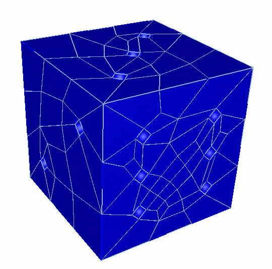
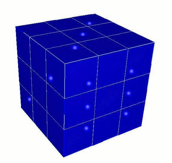
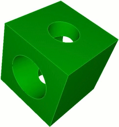
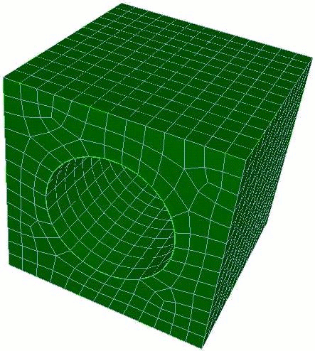
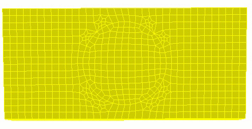
Shown below is a model of a game die meshed with identical mesh size, with details included and removed.
Note: "Small" Measurement
Automatic detail suppression identifies "small" geometric entities by comparing their "size" to the mesh size assigned by the user to the entity. Anything smaller than that size is designated as a detail and put in the appropriate detail group (e.g. detail_faces, detail_edges, etc.). The size of an edge is simply its arc length; surfaces and volumes are measured using the "hydraulic diameter" (see next note).
Note: Hydraulic Diameter
The hydraulic diameter of a surface is computed as 4.0*A/P, where A is the surface area and P is the summed arc lengths of all bounding curves. For circles, the hydraulic diameter is the circle diameter; for squares, it is the length of the bounding curves. Similarly, for volumes, the hydraulic diameter is computed as 6.0*V/A, which evaluates to the diameter and bounding curve length for perfect spheres and cubes, respectively.
15.1.2 Automatic Geometry Decomposition
Set Developer Commands {On|OFF}
Cut Body <body_id_range> [Trace {on|off}] [Depth <cut_depth>]
15.1.3 Cohesive Elements
Set Developer Commands {On|OFF}
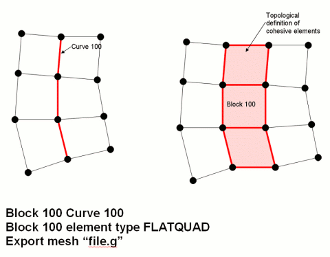
Cubit supports 2D cohesive regions.Cohesive elements are implemented in Cubit as element blocks with an element type of FLATQUAD.The cohesive region is identified by assigning geometric curves to the FLATQUAD element block.When the element block is exported, each edge on the specified curves is represented in the exported file as a 4-noded quadrilateral element with zero area.The quadrilateral element is formed by duplicating each node in the original edge and then connecting the two original and two duplicate nodes to form a zero-area quadrilateral.
The image below shows how a FLATQUAD is represented in an exported mesh file.The figure on the left is how the mesh appears in Cubit.The figure on the right is how the mesh appears in the output file.Note that the figure on the right is a topological representation, not a true geometric representation.In reality, the nodes on the left side of block 100 are coincident with the nodes on the right side of block 100, causing the pink elements to have zero area.
15.1.3.1 Multiple Curves in FLATQUAD Blocks
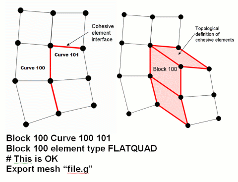
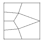
Multiple curves may be assigned to a single FLATQUAD element block, as long as the curves do not form a branching path.The figure below, for example, shows an acceptable configuration of multiple curves.
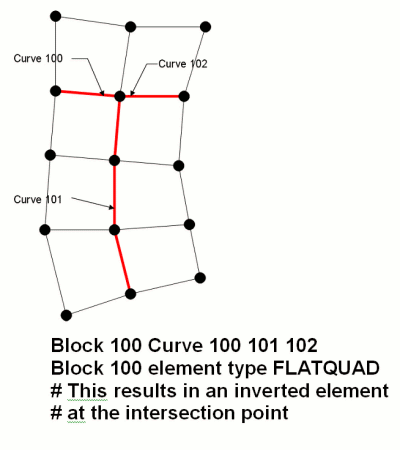
Although multiple curves may be assigned to a single cohesive block, the curves assigned to a block of type FLATQUAD must not branch.A branch occurs whenever three or more curves share a common vertex, as shown in the figure below.This will be corrected in future versions of Cubit.
15.1.4 Deleting Mesh Elements
Set Developer Commands {On|OFF}
When deleting elements, the default behavior will be that the child mesh entities will be deleted when they become orphaned. For example, when a hex is deleted, if its faces, edges and vertices are no longer used by adjacent hex elements, then they will also be deleted. The no_propagate option will leave any child mesh entities regardless if they become orphaned.
The delete command removes one or more mesh entities from an existing mesh. Additional mesh entities may be deleted as well depending on the particular form of the command. Exactly which entities are removed is explained in the following descriptions.
To delete a hex or tet:
In the Command Line, type set developer commands on (Set Dev On).
On the Command Panel, click on Mesh.
Click on Hex or Tet.
Click on the Delete action button.
Enter the appropriate values for Hex ID(s) or Tet ID(s). This can also be done using the Pick Widget function.
Click Apply..
Delete {Hex|Tet} <range> [No_Propagate]
Delete Wedge <range>
To delete a quad or tri:
In the Command Line, type set developer commands on (Set Dev On).
On the Command Panel, click on Mesh.
Click on Quad or Tri.
Click on the Delete action button.
Enter the appropriate values for Quad ID(s) or Tri ID(s). This can also be done using the Pick Widget function.
Click Apply..
Delete {Face|Tri} <range> [No_Propagate]
To delete an edge:
In the Command Line, type set developer commands on (Set Dev On).
On the Command Panel, click on Mesh and then Edge.
Click on the Delete action button.
Enter the appropriate values for Edge ID(s). This can also be done using the Pick Widget function.
Click Apply..
Delete Edge <range> [No_Propagate]
To delete a node:
In the Command Line, type set developer commands on (Set Dev On).
On the Command Panel, click on Mesh and then Node.
Click on the Delete action button.
Enter the appropriate values for Node ID(s). This can also be done using the Pick Widget function.
Click Apply..
Delete Node <range>
15.1.5 FeatureSize
Set Developer Commands {On|OFF}
Summary: Meshes a curve based on its proximity to nearby geometry and size of nearby geometric features. This is an alpha feature and should be used with caution.
Curve <range> Scheme Featuresize
Curve <range> Density <density_factor>
The user may also automatically bias the mesh from small elements near complicated geometry to large elements near expanses of simple geometry. Meshing a curve with scheme featuresize places nodes roughly proportional to the distance from the node to a piece of geometry that is foreign to the curve. Foreign means that the geometric entity doesn’t contain the curve, or any of its vertices (i.e. the entity’s intersection with the curve is empty). It is known that featuresize is a continuous function that varies slowly. Featuresize meshing is very automatic and integrated with interval matching. Featuresize meshing works well with paving, and in some cases with structured surface-meshing schemes (map, submap) as well.
If desired, the user may specify the exact or goal number of intervals with a size or interval command, and then the featuresize function will be used to space the nodes.
Curve <range> Density <density_factor>
15.1.6 Geometry Tolerant Meshing
Set Developer Commands {On|OFF}
Mesh Type: Triangle, Tetrahedral, Quadrilateral
Summary:The geometry tolerant meshing algorithm takes a volume and generates a mesh by ignoring small features, gaps, slivers, and surface alignment problems in the geometry.
To create a tolerant mesh:
In the Command Line, type set developer commands on (Set Dev On).
On the Command Panel, click on Mesh and then Volume.
Click on the Tolerant Mesh action button.
Select Tolerant Mesh from the drop-down menu.
Enter the appropriate values for Volume ID(s). This can also be done using the Pick Widget function.
Select Triangle, Tetrahedal or Quadrilateral from the Algorithm mennu.
Select FEM, New or Old.
Enter the appropriate value for Tolerance Fraction.
Click Apply.
Mesh Tolerant Volume <range> {Triangle|Tet|Quadrilateral} {Free} {Fraction <number>} {Fem|New|Old}
In the Command Line, type set developer commands on (Set Dev On).
On the Command Panel, click on Mesh and then Volume.
Click on the Tolerant Mesh action button.
Select Fix/Free Entities from the drop-down menu.
Select Fix or Free.
Select Volume, Surface, Curve or Vertext from the drop-down menu and enter the appropriate value.
Click Apply.
Mesh Tolerant [Fix|Free] [Volume|Surface|Curve|Vertex] <range>
In the Command Line, type set developer commands on (Set Dev On).
On the Command Panel, click on Mesh and then Volume.
Click on the Tolerant Mesh action button.
Select Visualize Mesh from the drop-down menu.
Enter the appropriate value for Volume ID(s). This can also be done using the Pick Widget function.
Click Apply.
Mesh Tolerant Volume <range> Facet
Many geometric assemblies contain imperfections or small features that hinder mesh generation. These imperfections can be caused by excessive detail, data format translation errors, poorly constructed initial models and a variety of other factors. Rather than performing time-consuming geometry operations to remove these features, the geometry tolerant meshing scheme will be "tolerant" of these details, and generate a mesh that ignores features below a certain size threshold. Since there may be features under that threshold which the user desires to retain in the final mesh, there is also the option to "fix" certain geometric features so they are retained in the final mesh.
The basic approach to this method involves using the model’s facet data to create a a loose representation of the geometry using the geometry’s native kernel. This faceted representation is modified to conform to the features of the model which are either "fixed" by the user, or larger than a user-provided size. Small edges are removed from the mesh, and long edges are refined. The final mesh is created by iterating over patches of triangles from the initial mesh, and re-meshing these patches with good quality elements.
15.1.6.1 Initial Mesh Size
An initial mesh size must be input by the user before using the geometry tolerant meshing scheme. This initial mesh size is important to the final outcome. If the edge lengths are initially much smaller than the mesh size, the algorithm will have to do significant work to coarsen the mesh. On the other hand, if the mesh edges are too large, the final mesh will either not capture the geometry well, or the geometry information will, later, have to be extracted from the original model. The mesh sizing is set using the regular interval specification methods.
The sizing algorithm will assign a mesh size to each geometry element. The initial faceted mesh will be a loose approximation of these sizes.
15.1.6.2 Fixing a Geometric Entity
Mesh Tolerant Fix [Volume|Surface|Curve|Vertex] <range>
Mesh Tolerant Free [Volume|Surface|Curve|Vertex] <range>
15.1.6.3 Tolerance Fraction
The user-provided fraction controls which of non-fixed features are large enough to be included in the final mesh. It is possible for the tolerance fraction to be any number greater than zero, but in practice this number is usually less than 1. The fraction can be thought of as the percentage of the mesh size that defines a tolerable feature. After the initial faceted mesh has been created, the algorithm will loop through all of the mesh edges on the entity. Mesh edges which are smaller than the value of the (mesh size)*(tolerance fraction) will be removed if they do not belong to a fixed edge. In addition, each triangle on the surface is compared to the tolerant size to determine if it is too small. The tolerance size for a triangle is the minimum of the tolerance for the vertices. If the altitude of the triangles is shorter than that tolerance, the shortest edge of the triangle is removed. For example, if the following commands were issued:
volume 1 size 0.5
mesh tolerant volume 1 fraction 0.25
the tolerance value in the above example would be 0.5*0.25 or 0.125. Any mesh edges (from the initial faceted representation) that are smaller than 0.125 would be removed, unless fixed. Like the initial mesh size, the choice of an appropriate tolerance fraction for a given mesh size is an important to the final outcome. A larger tolerance fraction will remove more small features and possibly require you to specify more fixed edges explicitly. A smaller tolerance fraction will respect most of the original geometry, but may include features you wish to ignore.
15.1.6.4 Creating the tolerant mesh
A typical sequence of events to create a tolerant mesh would be to:
Specify a mesh size
Determine tolerance fraction
Fix geometric entities that have features that are smaller than that mesh size * tolerance fraction using the mesh tolerant fix command
Mesh the geometry using the Mesh Tolerant command
Mesh Tolerant Volume <range> {Triangle|Tet|Quadrilateral} {Free} {Fraction <number>} {Fem|New|Old}
Mesh Tolerant Volume <range> Facet
15.1.6.5 Fem/New/Old Options
The FEM/New/Old options refer to how the initial triangle surface mesh is generated. The FEM option will use Cubit’ advancing front trimesh scheme as the initial surface mesh. This is more likely to produce better quality elements, but less likely to succeed in meshing. The new and old options will both create a mesh by using the geometry engine’s facetted representaton. There is a slight variation in how the mesh is created, however. The new option will create the facet mesh for the entire volume using a method that requires no stitching, while the old option will loop over surfaces, assigning sizes and meshing them individually.
15.1.6.6 Free Mesh vs. Mesh-Based Geometry
The free option of the tolerant meshing algorithm refers to whether the final mesh is a free mesh, or if it attempts to create new mesh-based geometry to conform to the mesh. If the free option is included, the final mesh will be a free mesh, without any associated geometry. The mesh elements will be automatically placed into a group named ’tolerant_mesh_group’. All surface meshes will be placed in groups named ’mesh_from_surface_<id>’ where <id> refers to the former surface id number. If the free option is omitted, or the "Create Mesh Based Geometry" button on the GUI is checked, the algorithm will create new mesh-based geometry that resides on top of the old geometry and contains the new mesh.
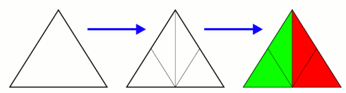
15.1.6.7 Quadrilateral Surface Mesh
Figure 592: A triangle split into 4 triangles can then be paired into two quadrilaterals, the red and green shown on the right.
15.1.6.8 Examples
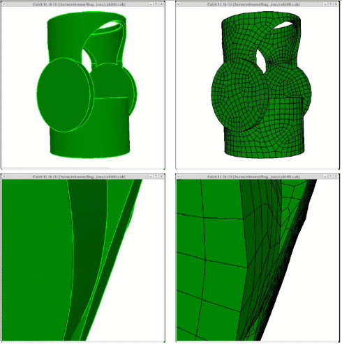
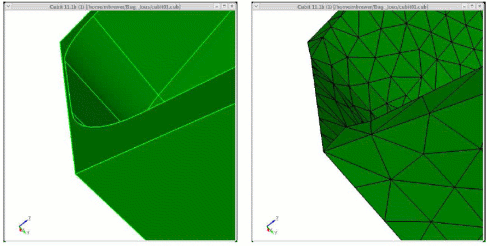
Figure 593: Demonstration of the geometry tolerant meshing algorithm to remove a small groove.
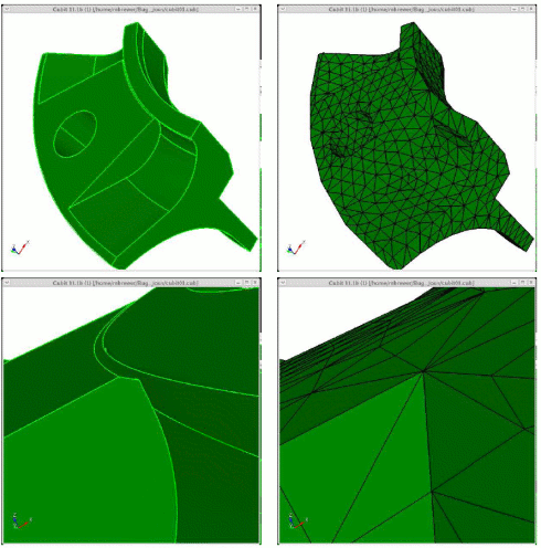
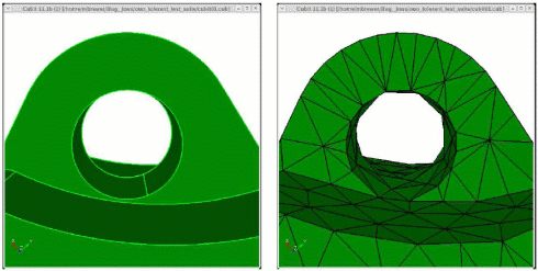
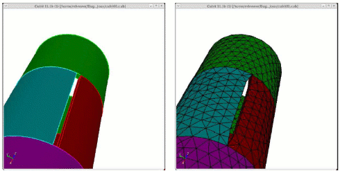
Figure 596: Quadrilateral shell mesh generated using geometry tolerant meshing scheme. Note that no hexahedral elements were generated.
15.1.6.9 Limitations
15.1.6.9.1 Accumulated geometric error
15.1.6.9.2 Loss of Resolution due to initial faceting
15.1.6.9.3 Surface to Surface proximity
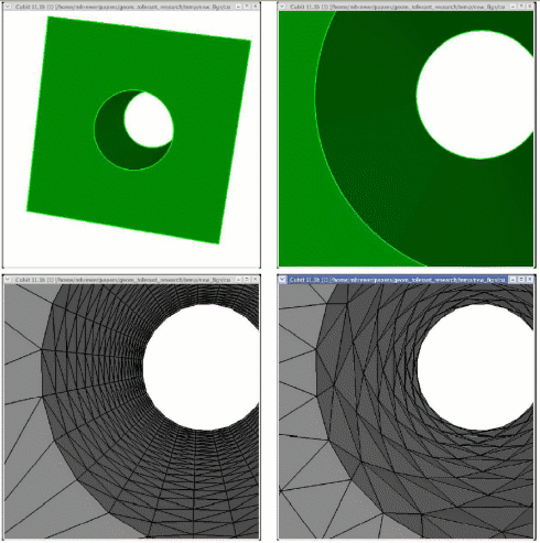
Figure 599: Demonstration of geometry-tolerant meshing algorithm failing to recognize a thin region that has no small edges or facets
15.1.6.9.4 Mesh size on fixed geometry entities
If a geometric entity is fixed, the original facet edges on that entity are not collapsed regardless of how small, relative to the target mesh size, they may be. Therefore, in the current approach, there is no mechanism for coarsening the feature mesh edges in these regions.
15.1.7 Mesh Cutting
Note: This feature is under development. The command to enable or disable features under development is:
set developer commands {on|OFF}
The term "mesh cutting" refers to modifying an existing mesh by moving nodes to a cutting entity and modifying the connectivity of the mesh so that the original mesh fits a new geometry. The behavior of mesh cutting is intended to be similar to web cutting in that the process results in a decomposition of the original geometry. The difference is that the decomposition is performed on meshed geometry and results in the creation of virtual geometry partitions. The underlying ACIS body remains unchanged. The user has the option to determine what is partitioned during mesh cutting: the volume, the surfaces only, or nothing.
The current scope of mesh cutting is limited to cutting hex meshed volumes with planes and extended surfaces. These cutting entities are also limited in that mesh cutting will not work if they pass through a vertex at the end of more than two curves. Mesh cutting does not work on tet meshes or surface meshes.
The steps of mesh cutting include:
Create a starting mesh. This mesh is typically simpler than the desired final mesh and can be created with sweeping, mapping, or some other available meshing algorithm. Currently, the starting mesh must be a single volume: mesh cutting does not handle merged volumes or assemblies.
Create a cutting entity that can be used to capture the new detail in the mesh. Currently, mesh cutting works with planes or sheets extended from surfaces. It is important to note that if an extended surface is used, mesh cutting will not capture any geometric features (curves or vertices) of the surface.
Issue the command to cut the mesh. The meshcut commands are similar in syntax and behavior to the webcut commands.
The following entities with the associated commands are available for mesh cutting:
15.1.7.1 Coordinate Plane
Meshcut Volume <range> Plane {xplane|yplane|zplane} [offset <dist>]
15.1.7.2 Planar Surface
Meshcut Volume <range> Plane Surface <surface_id>
15.1.7.3 Plane from 3 points
Meshcut Volume <range> Plane Node <3_node_ids>
15.1.7.4 Extended Surface
Meshcut Volume <range> Sheet [Extended From] Surface <surface_id>
Composite closest_pt surface <id> gme
15.1.7.5 Meshcut Options
The following options can be used with all the meshcut commands:
[PARTITION VOLUME|partition surface|no_partition]
[no_refine]: This option tells mesh cutting not to refine the mesh around the cutting entity.
[no_smooth]: This option tells mesh cutting not to perform the final smoothing step after the cut has been made.
15.1.7.6 Meshcutting Scope
The following is a list of the current scope and limitations of meshcutting.
Meshcutting only works on hex meshes.
Meshcutting only works for single volumes. It currently does not handle assembly meshes.
Currently, only planes and extended surfaces can be used as the cutting entity.
Curves and vertices on the cutting entity will not be captured in the mesh.
Meshcutting will not work if the cutting entity passes through a meshed vertex that is at the end of more than two curves.
The resolution of the mesh determines how well a non-planar cutting entity will be captured in the resulting mesh. Small features and high curvature will not be captured by a coarse mesh.
Spline surfaces are limited in extent and may not give expected results if used as an extended cutting surface.
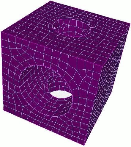
15.1.7.7 Meshcutting Example
Cubit> create brick x 10
Cubit> create cylinder radius 3 z 15
Cubit> subtract 2 from 1
Cubit> volume 1 scheme sweep
Cubit> volume 1 size .75
Cubit> mesh volume 1
Cubit> create cylinder radius 2 z 15
Cubit> rotate body 3 about x angle 90
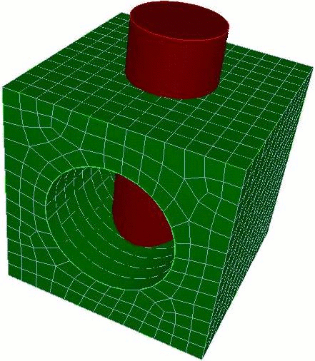
Cubit> meshcut vol 1 sheet surface 13
Cubit> draw volume 1 4 5
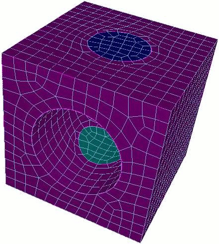
Cubit> delete mesh vol 4 5 propagate
Cubit> draw volume 1
15.1.8 Mesh Grafting
Set Developer Commands {On|OFF}
Graft {Surface <range> | Volume <id>} onto Volume <id> [no_refine] [no_smooth]
15.1.8.1 Grafting Options
[no_refine]: This option tells grafting not to modify the connectivity of the original mesh. The mesh is still adjusted to fit the boundary of the branch surface but no new elements are added.
[no_smooth]: This option tells grafting not to perform the final smoothing of the modified surface or volume mesh.
15.1.8.2 Grafting Scope
The following is a list describing the current scope and limitations of grafting:
Grafting only works on volumes meshed with hex elements.
The unmeshed branch surface cannot have any point outside the boundary of the meshed trunk surface.
Grafting may have difficulty with branch surfaces that are very thin with respect to the element size of the meshed surface or that have sharp angles.
If grafting fails some of the nodes of the original mesh may have been moved. Check the mesh quality and re-smooth if needed.
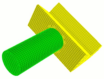
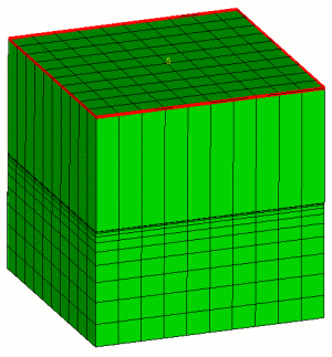
Grafting Example
This example shows the four basic steps of grafting:
Partition the geometry (optional).
Mesh the trunk volume.
Graft the branch volume onto the trunk volume.
Mesh the branch volume.
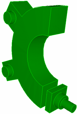
Step 1: Partition the geometry
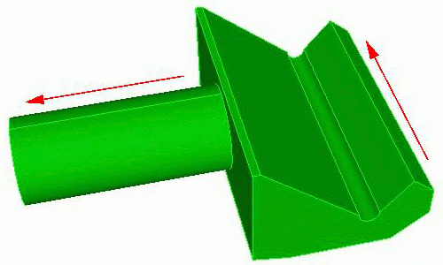
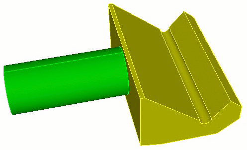
Step 2: Mesh the trunk volume.
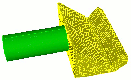
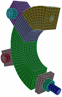
Step 3: Graft the branch onto the trunk
Step 4: Mesh the branch volume.
15.1.9 Optimize Jacobian
Set Developer Commands {On|OFF}
Summary: Produces locally-uniform hex meshes by optimizing element Jacobians
Volume <range> Smooth Scheme Optimize Jacobian [param]
The Optimize Jacobian method minimizes the sum of the squares of the Jacobians (i.e., volumes) attached to the smooth node. Meshes smoothed by this means tend to have locally-uniform hex volumes.
The parameter <param> has a default value of 1, meaning that the method will attempt to make local volumes equal. The parameter, which should always be between 1 and 2 (with 1.05 recommended), can be used to sacrifice local volume equality in favor of moving towards meshes with all-positive Jacobians.
15.1.10 Randomize
Set Developer Commands {On|OFF}
Summary: Randomizes the placement of nodes on a geometry entity
{Surface|Volume} <range> Smooth Scheme Randomize [percent]
15.1.11 Refine Mesh Boundary
Note: This feature is under development. The command to enable or disable features under development is:
set developer commands {on|OFF}
Refine Mesh Boundary Surface <range> Volume <id> {Bias <double>} {First_delta <double> | Thickness <double>} [Layer <num_layers=1>] [SMOOTH|No_smooth]
15.1.12 Super Sizing Function
Set Developer Commands {On|OFF}
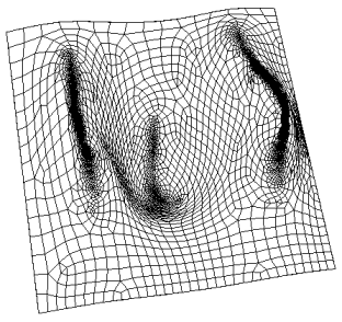
Figure 611: NURB mesh with super sizing function, 34 by 16 density
15.1.13 Test Sizing Function
Note: This feature is under development. The command to enable or disable features under development is:
set developer commands {on|OFF}
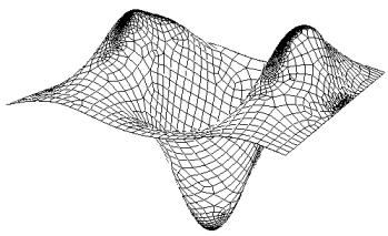
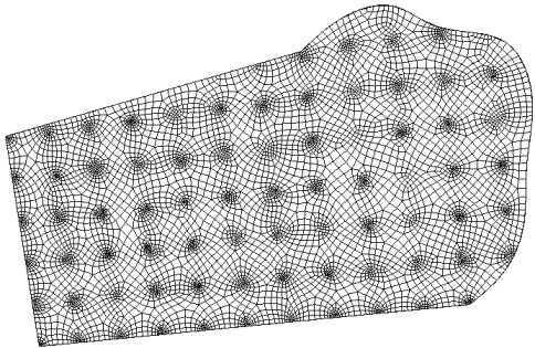
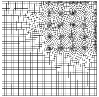
The test sizing function is a hard wired numerical function used to demonstrate the transitional effect of sizing function-based and adaptive paving. The function is a periodic function which is repeated in 50x50 unit intervals on a 2D surface in the first quadrant (x > 0, y > 0, z = 0). This is an alpha feature and should be used with caution. An example of a surface meshed with this sizing function is shown in Figure 612 and Figure 613.
 }
}15.1.14 Transition
Note: This feature is under development. The command to enable or disable features under development is:
set developer commands {on|OFF}
Applies to: Surfaces
Summary: Produces a specified transition mesh for specific situations
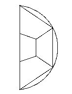
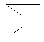
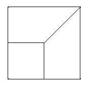
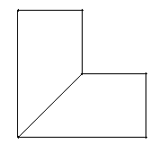
Surface <range> Scheme Transition {Triangle|Half_circle|Three_to_one|Two_to_one|Convex_corner|Four_to_two} [Source Curve <id>] [Source Vertex <id>]
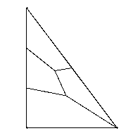
The transition scheme supplies a set of transition primitives which serve to transition a mesh from one density to another across a given surface. The six transition sub-types are demonstrated here.
| |
| |
| |
| |
| |
|
The user also has the option of specifying a source curve and/or a source vertex. The rules for these specifications are as follows
If both a curve and vertex are specified, the vertex must be on the curve.
The Convex_corner sub-type does not allow a source curve.
The Four_to_two sub-type does not allow a source vertex.
The source curve will be the curve that will be given the fewest intervals.
The source vertex will specify which corner will be used for the scheme, in cases where this makes sense (primarily in the Triangle, and Two_to_one cases).
If none of the optional information is given, the program will assign the source curve to be the shortest one on the face, in keeping with the most probable
15.1.15 Triangle Mesh Coarsening
Set Developer Commands {On|OFF}
Coarsen {Node|Edge|Tri} <range> {Factor|Size <double> [Bias <double>]} [Depth <int>|Radius <double>] [Sizing_Function] [no_smooth]
Coarsen {Vertex|Curve|Surface} <range> {Factor|Size<double> [Bias<double>]} [Depth<int>|Radius<double>] [Sizing_Function] [no_smooth]
To use these commands, first select mesh or geometric entities at which you would like to perform coarsening. Coarsening operations will be applied to all mesh entities associated with or within proximity of the entities. The all keyword may be used to uniformly coarsen all triangles in the model.
Following is a description of each of the coarsen options:
factor
size, bias
The Size and Bias options are useful when a specific element size is desired at a known location. This might be used for locally coarsening around a vertex or curve. The Bias argument can be used with the Size option to define the rate at which the element sizes will change to meet the existing element sizes on the model. Valid input values for Bias are greater than 1.0 and represent the maximum change in element size from one element to the next. Since coarsening is a discrete operation, the Size and Bias options can only approximate the desired input values. This may cause apparent discontinuities in the element sizes. Using the default smooth option can lessen this effect. It should also be noted that the Size option is exclusive of the Factor option. Either Factor or Size can be specified, but not both.
depth
radius
Instead of specifying the number of elements to describe how far to propagate the coarsening, a real Radius may be entered.
sizing function
Coarsening may also be controlled by a sizing function. Cubit uses sizing functions to control the local density of a mesh. Various options for setting up a sizing function are provided, including importing scalar field data from an exodus file. In order to use this option, a sizing function must first be specified on the surface on which the coarsening will be applied. See Adaptive Meshing for a description of how to define a sizing function.
no_smooth
The default mode for coarsening operations is to perform smoothing after coarsening the elements. This will generally provide better quality elements. In some cases it may be necessary to retain the original node locations after coarsening. The no_smooth option provides this capability.
15.1.16 Whisker Weave
Note: This feature is under development. The command to enable or disable features under development is:
set developer commands {on|OFF}
Applies to: Volumes
Summary: Research algorithm for all-hexahedral meshing of arbitrary 3D volumes
Volume <range> Scheme Weave
Pillow Volume <range>
{Volume|Surface|Curve} <range> Mesh [Fixed|Free]
Set AutoWeaveShrink [on|off]
Set Statelist [on|off]
Whisker Weaving (Tautges, 96; Tautges, 95; Folwell, 98) is a volume meshing algorithm currently being researched and is not released for general use. However, daring users may find the current form of the algorithm useful for mostly-convex geometries.
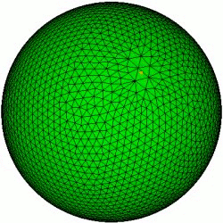
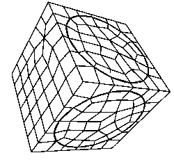
Whisker Weaving holds the promise of being able to fill arbitrary geometries with hexahedra that conform to a fixed surface mesh. The algorithm is based on the rich information contained in the Spatial Twist Continuum (STC) (Murdoch, 95), which is the grouping of the dual of an all-hexahedral mesh into an arrangement of surfaces called sheets. Given a bounding quadrilateral surface mesh, Whisker Weaving constructs sheets advancing from the boundary inward. The sheets are then modified so that the arrangement dualizes to a well defined hexahedral mesh. Once the primal hex-mesh is generated, interior node positions are generated by smoothing.
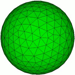
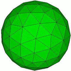
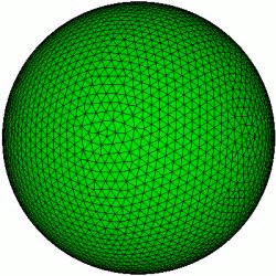
Examples of meshes generated using the whisker weaving algorithm are shown in the following figure.
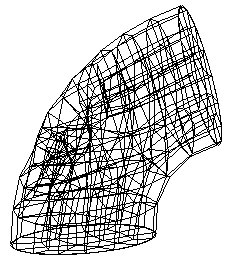
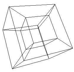
Figure 616: Some simple Whisker Weaving meshes with good quality
15.1.16.1 Whisker Weaving Basic Commands
The basic steps for meshing a volume with Whisker Weaving are the following:
Volume <range> Scheme Weave
Mesh Volume <range>
Pillow Volume <range>
Volume <range> Smooth Scheme Condition Number
smooth volume <range>
15.1.16.2 Whisker Weaving Options
Currently, Whisker Weaving relies on being able to perturb the bounding quadrilateral mesh. However, a bounding surface’s mesh will not be changed if it is contained in another volume that is already meshed.
{Volume|Surface|Curve} <range> Mesh [Fixed|Free]
Set AutoWeaveShrink [on|off]
Set Statelist [on|off]