4.6 Geometry Cleanup and Defeaturing
Frequently, models imported from various CAD platforms either provide too much detail for mesh generation and analysis, or the geometric representation is deficient. These deficiencies can often be overcome with small changes to the model. Several tools are provided in Cubit for this purpose.
4.6.1 Automatic Geometry Clean-up
The automated geometry clean-up commands are used to automatically clean up geometry in preparation for meshing. These commands are built in to the ITEM interface, but they can also be used on their own. Note: some of these operations will create virtual geometry.
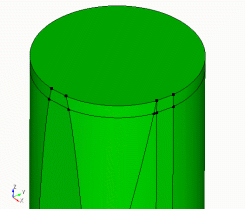
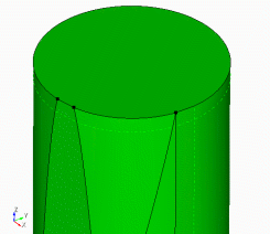
4.6.1.1 Automatic Forced Sweepability
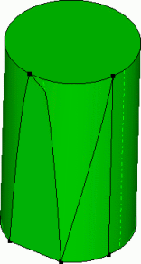
In some cases, a volume can be "forced" into a sweepable configuration by compositing surfaces on the linking surfaces. The automatic forced sweep command will attempt to automatically composite linking surfaces together to create a sweepable topology. This command can be useful in cases where there are many linking surfaces that prohibit sweepability and are not needed to define the mesh. It is assumed that the user has assigned the source and target surfaces for the sweep prior to calling this function. Cubit will try to composite linking surfaces together to get rid of problems such as 1) non-submappable linking surfaces, 2) interior angles between curves of a surface that deviate far from multiples of 90 degrees, and 3) surfaces with curves smaller than the small curve size, if a small curve size is specified. This command is incorporated into the ITEM GUI, but is also available from the command line using the following command syntax.
To use automatic forced sweepability
On the Command Panel, click on Geometry and then Volume.
Click on the Modify action button.
Select Auto Clean from the drop-down menu.
Enter in the appropriate values for Volume ID(s). This can also be done using the Pick Widget function.
Enter in the appropriate value for Small Feature Threshold Size.
Click Force Sweepability from the Select Auto Clean Method menu.
Click Apply.
Auto_clean Volume <id_range> Force_sweepability [Small_curve_size <val>]
4.6.1.1.1 Example
auto_clean volume 1 force_sweepability small_curve_size .7
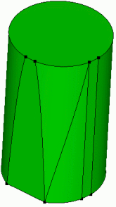
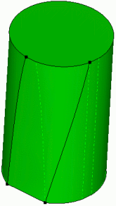
Figure 154: Linking surfaces are composited to force a sweepable volume topology

4.6.1.2 Automatic Surface Split
This auto clean command will attempt to automatically split narrow regions of surfaces. In this context, any surface that contains a portion that narrows down to a small angle is considered a narrow region. The command will use the split command from the underlying solid modeling kernel. The user specifies a size that defines what is narrow. This command also propagates the splits to neighboring narrow surfaces. This command is usually used as a preprocessor to the "tweak remove_topology" command but can also be used on its own.
To automatically split narrow regions of surfaces
On the Command Panel, click on Geometry and then Volume.
Click on the Modify action button.
Select Auto Clean from the drop-down menu.
Enter in the appropriate values for Volume ID(s). This can also be done using the Pick Widget function.
Enter in the appropriate value for Small Feature Threshold Size.
Click Split Narrow Regions from the Select Auto Clean Method menu.
Click Apply.
Auto_clean Volume <id_range> Split_narrow_regions Narrow_size <val>
4.6.1.2.1 Example

4.6.1.3 Automatic Small Curve Removal
The automatic small curve removal command uses composites and collapse curves commands to automatically remove small curves from a volume. This is useful for removing small or unnecessary details from a model to facilitate meshing algorithms. The user enters a small curve size. Any curve smaller than this specified size will be removed. This command is issued from the ITEM toolbar. More information can be found by reading the section entitled Small Details in the Model in the ITEM documentation. This command can also be called from the command line. The syntax of this command is:
To remove small curves from a volume
On the Command Panel, click on Geometry and then Volume.
Click on the Modify action button.
Select Auto Clean from the drop-down menu.
Enter in the appropriate values for Volume ID(s). This can also be done using the Pick Widget function.
Enter in the appropriate value for Small Feature Threshold Size.
Click Small Curves from the Select Auto Clean Method menu.
Click Apply.
Auto_clean Volume <id_range> Small_curves Small_curve_size <val>
The automatic curve removal should be used with caution, as the user has little control over how curves are removed.
Example:
auto_clean volume 1 small_curves small_curve_size .7
4.6.1.4 Automatic Small Surface Removal
This auto clean command will attempt to remove small and narrow surfaces from the model by compositing them with neighboring surfaces. The user specifies a small curve size value. This value is used in two different ways. First, a small area is calculated as the small curve size squared. This value is used to compare against when looking for small surfaces. The small curve size is also used to identify surfaces that are narrower than the small curve size.
To remove small and narrow surfaces from the model
On the Command Panel, click on Geometry and then Volume.
Click on the Modify action button.
Select Auto Clean from the drop-down menu.
Enter in the appropriate values for Volume ID(s). This can also be done using the Pick Widget function.
Enter in the appropriate value for Small Feature Threshold Size.
Click Small Surfaces from the Select Auto Clean Method menu.
Click Apply.
Auto_clean Volume <id_range> Small_surfaces Small_curve_size <val>
4.6.1.4.1 Example
4.6.2 Healing
Healing is an optional module that detects and fixes ACIS models.
It is possible to create ACIS models that are not accurate enough for ACIS to process. This most often happens when geometry is created in some other modeling system and translated into an ACIS model. Such models may be imprecise due to the inherent numerical limitations of their parent systems, or due to limitations of data transfer through neutral file formats. This imprecision can also result when an ACIS model is created at a different tolerance from the current tolerance settings. This imprecision leads to problems such as geometric errors in entities, gaps between entities, and the absence of connectivity information (topology). Since ACIS is a high precision modeler, it expects all entities to satisfy stringent data integrity checks for the proper functioning of its algorithms. Therefore, if such imprecise models must be processed by an ACIS based system, "healing" of such models is necessary to establish the desired precision and accuracy.
4.6.2.1 Analyzing Geometry
The following operation analyzes the ACIS geometry and will indicate problems detected
On the Command Panel, click on Geometry and then Volume.
Click on the Modify action button.
Select Heal from the drop-down menu.
Select Analyze or Autoheal.
Enter in the Filename.
Enter in any other appropriate settings from this menu.
Click Apply.
Healer Analyze Body <id_range> [Logfile [’filename’] [Display]]
The outputs include an estimate of the percentage of good geometry in each body. The optional logfile will include detailed information about the geometry analysis. By default Cubit will also highlight the bad geometry in the graphics and give a printed summary indicating which entities are "bad".Sample output from this command is shown below:
Percentage good geometry in Body 9: 98%
HEALER ANALYSIS SUMMARY:
—
Analyzed 1 Body: 9
Found 2 bad Vertices: 51, 52
Found 3 bad Curves: 76, 77, 80
Found 2 bad CoEdges. The Curves are: 76
Found 1 Bodies with problems: 9
Journaled Command: healer analyze body 9
It is not necessary to analyze the geometry before healing; however, it can be useful to analyze first rather than healing unnecessarily. Also, that healer analysis can take a bit of time, depending on the complexity of the geometry and how bad the geometry is.
The validate geometry commands work independently of the healer and give more detailed information.
4.6.2.1.1 Healer Settings
Healer Set OnShow {Highlight|Draw|None}
Healer Set OnShow {Badvertices|Badcurves|Badcoedges|Badbodies|All} {On|Off}
Healer Set OnShow Summary {On|Off}
These settings allow you to highlight, draw or ignore the bad entities in the graphics. You can control which entity types to display, as well as whether or not to show the printed summary at the end of analysis.
Healer Show Body <id_list>
4.6.2.2 Auto Healing
Healing is an extremely complex process. The general steps to healing are:
Preprocess - trim overhanging surfaces and clean topology (remove small curves and surfaces).
Simplify - converts splines to analytic representations, if possible.
Stitch - geometry cleanup and stitching loose surfaces together to form bodies.
Geometry Build - repairing and building geometry to correct gaps in the model.
Post-Process - calculating pcurves and further repairing bad geometry.
Make Tolerant Curves & Vertices - a last optional step that allows special handling of unhealed entities for booleans - allowing inaccurate geometry to be tolerated.
Autohealing makes these steps automatic with the following command:
To use Autohealing
On the Command Panel, click on Geometry and then Volume.
Click on the Modify action button.
Select Heal from the drop-down menu.
Select Autoheal.
Enter in the Filename.
Enter in any other appropriate settings from this menu.
Click Apply.
Healer Autoheal Body <id_range> [Rebuild] [Keep] [Maketolerant] [Logfile [’logfilename’] [Display]]
The keep option will retain the original body, putting the resulting healed body in a new body.
The maketolerant option will make the edges tolerant if ACIS is unable to heal them. This can result in successful booleans even if the body cannot be fully healed - ACIS can then sometimes "tolerate" the bad geometry. Note that the healer analyze command will still show these curves as "bad", even though they are tolerant. The validate geometry commands however take this into consideration.
The output from the autoheal command can be written to a file using the logfile option; the default file name is autoheal.log.The display option works as before, displaying the results in a window in the GUI version of Cubit.
4.6.2.3 Healing Attributes
Healer CleanAtt Body <id_range>
Healer Set CleanAtt {On|Off}
4.6.2.4 Spline Removal
healer default simplifytol .1
healer autoheal body 1
Healer Force {Plane|Cylinder|Cone|Sphere|Torus} Surface <id_list> [Keep]
Execute Filter Curve Geometry_type Spline
4.6.2.5 What if Healing is Unsuccessful?
The ACIS healing module is under continued development and is improving with every release. However, there will often be situations where healing is unable to fully correct the geometry. This might be okay, as meshing is rarely affected by the small inaccuracies healing addresses. However, boolean operations on the geometry can fail if the bad geometry must be processed by the operation (i.e., a webcut must cut through a bad curve or vertex).
Here are some possible methods to fix this bad geometry:
Return to the source of the geometry (i.e., Pro/ENGINEER) and increase the accuracy. Re-export the geometry.
Heal again using the rebuild option.
Heal again using the make tolerant option.
Remove the offending surface from the body (using the remove surface command), then construct new surfaces from existing curves and combine the body back together.
Composite the surfaces over the bad area, mesh and create a net surface from the composite, remove the bad surfaces and combine.
Export the geometry as IGES, import the IGES file into a new model and look for double surfaces or surfaces that show up at odd angles using the find overlap commands. Delete and recreate surfaces as needed and combine the surfaces back together into a body.
Contact the development team mailto:support@coreform.com) if you need further help with fixing bad geometry.
4.6.3 Removing Geometric Features
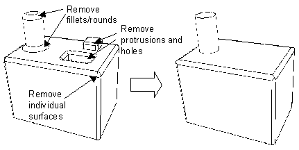
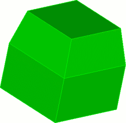
The Remove will remove surfaces or vertices from bodies. Adjacent surfaces or curves will be extended, where possible, to fill in remaining gaps. The remove command is useful for replacing filleted edges with sharp corners.
4.6.3.1 Removing Surfaces
The remove surface command removes surfaces from bodies. By default, it attempts to extend the adjoining surfaces to fill the resultant gap. This is a useful way to remove fillets and rounds and other features such as bosses not needed for analysis. See Figure 158 for an example of this process.The syntax for this command is:
To remove a surface
On the Command Panel, click on Geometry and then Surface.
Click on the Modify action button.
Select Remove from the drop-down menu.
Enter the appropriate values for Surface ID(s). This can also be done using the Pick Widget function.
Enter any other appropriate settings from this menu.
Click Apply.
Remove Surface <id_range> [Blend_Chain] [cavity][EXTEND|Noextend] [Keepsurface] [Keep] [Individual]
The noextend qualifier prevents the adjoining surfaces from being extended, leaving a gap in the body. This is sometimes useful for repairing bad geometry - the surface can be rebuilt with surface from curves or a net surface, etc.., then combined back onto the body.
The keep option will retain the original body and put the results of the remove surface in a new body. The keepsurface option will retain the surface which was removed.
The individual option will remove surfaces one-by-one instead of as a group. If one removal fails, the rest are still attempted. Without the individual option, no surface is removed unless they are all able to be removed.
Theblend_chainoption will not only remove the selected surface but will also remove any surfaces belonging to the same blend chain. A blend is a non-planar surface such as a fillet that has a constant radius of curvature in at least one of its principal parametric directions. The blend chain includes all connected surfaces that share a common radius of curvature.
Thecavityoption can be used to remove all surfaces defining a hole or cavity. A cavity is defined as the collection of surfaces bounded by curves where the exterior angle is greater than 180 degrees. Designating the cavity option will automatically include all surfaces that are part of the cavity to which the surface belongs. If the surface does not belong to a cavity, this option will be ignored.
This command is identical to the Tweak Surface Remove command.
4.6.3.1.1 Remove Sliver Surface
This command uses the ACIS remove surface capability on surfaces that have area less than a specified area limit.When ACIS removes a surface it extends the adjoining surfaces and intersects them to fill the gap. If it is not possible to extend the surfaces or if the geometry is bad the command will fail. The syntax for this command is:
To remove slivers
On the Command Panel, click on Geometry and then Volume.
Click on the Modify action button.
Select Remove Slivers from the drop-down menu.
Enter the appropriate values for Volume ID(s). This can also be done using the Pick Widget function.
Enter the appropriate values for Area Limit.
Click Apply.
Remove Slivers Body <id_range> [EXTEND|Noextend] [Keepsurface] [Keep] [Arealimit [<double>]]
Default Arealimit = 0.1
The noextend, keepsurface and keep options operate as for the remove surface command.The arealimit option allows the user to set the area below which surfaces will be removed.
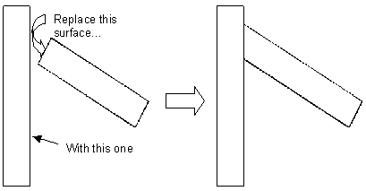
4.6.3.2 Removing Vertices
At times you may find that you have an extraneous vertex in your model. This would be a vertex connected to two and only two edges. This stray vertex can cause unwanted mesh artifacts, due to the fact that a mesh node MUST lie on this vertex, thereby disallowing the possibility of movement for better quality. Fortunately there is a relatively easy way of getting rid of this stray vertex using the tweak surface command.
To replace with a surface
On the Command Panel, click on Geometry and then Surface.
Click on the Modify action button.
Select Tweak from the drop-down menu.
Select Replace With Surface from the drop-down menu.
Enter the appropriate values for Surface ID(s) and replace with Surface ID. This can also be done using the Pick Widget function.
Click Apply.
Tweak Surface <id> Replace With Surface <same_id>
Note that you are replacing a surface with itself. In doing so, the geometry engine will do an intersection check on that surface, and should realize that the vertex doesn’t need to be there.
4.6.4 Tweaking Geometry
The tweaking commands modify models by moving, offsetting or replacing surfaces, curves, or volumes while extending the adjoining surfaces to fill the resulting gaps. This is useful for eliminating gaps between components, simplifying geometry or changing the dimensions of an object.
4.6.4.1 Tweaking Curves
This section details the options of the Tweak Curve commands available.
4.6.4.1.1 Create a Chamfer or Fillet
The Tweak Curve Chamfer or Fillet command is used to fillet or chamfer a curve. The radius value is the radius of the fillet arc or chamfer cut distance. The command syntax is:
To tweak a curve using the chamfer or fillet radius
On the Command Panel, click on Geometry and then Curve.
Click on the Modify action button.
Select Tweak from the drop-down menu.
Enter the appropriate value for Curve ID(s). This can also be done using the Pick Widget function.
Select Fillet Radius or Chamfer Radius from the drop-down menu.
Enter in the appropriate information.
Click Apply.
Tweak Curve <id_range> {Fillet|Chamfer} Radius <value> [Keep] [Preview]
Tweak Curve <id_list> Chamfer Radius <val1> [<val2>] [Keep] [Preview]
Figure 159 shows a brick (’br x 10’) chamfered with two different cut distances Tweak Curve 1 2 Chamfer Radius 2 4.
Tweak Curve <id> Fillet Radius <val1> [<val2>] [Keep] [Preview]
Figure 160 shows a brick (’br x 10’) filleted with different start and end radius values Tweak Curve 1 2 Chamfer Radius 2 4’.
4.6.4.1.2 Tweaking a Curve Using an Offset Distance
To tweak a curve using offset
On the Command Panel, click on Geometry and then Curve.
Click on the Modify action button.
Select Tweak from the drop-down menu.
Enter the appropriate value for Curve ID(s). This can also be done using the Pick Widget function.
Select Offset from the drop-down menu.
Enter in the appropriate Offset Value.
Click Apply.
tweak curve <id_list> offset <val> [curve <id_list> offset <val>] [curve <id_list> offset <val> ...] [keep] [preview]
4.6.4.1.3 Removing a Curve
To remove a curve
On the Command Panel, click on Geometry and then Curve.
Click on the Modify action button.
Select Tweak from the drop-down menu.
Enter the appropriate value for Curve ID(s). This can also be done using the Pick Widget function.
Select Remove from the drop-down menu.
Click Apply.
Tweak Curve <id_list> Remove [Keep] [Preview]
Similar to the Tweak Curve Remove command, the tweak curve remove function removes a specified curve from a sheet body. Figure 162 shows a simple example of removing a curve from a sheet body.
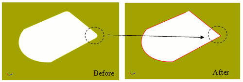
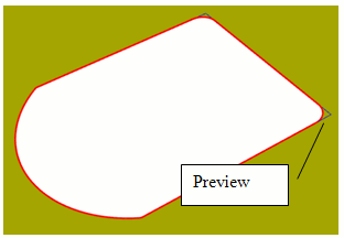
4.6.4.1.4 Tweaking a Curve Using Target Surfaces, Curves, or Plane
Use Tweak Curve Target to offset a curve to a specified surface, plane or curve. Figure 163 shows an example of tweaking a curve to several surfaces.
To tweak a curve using a target surface
On the Command Panel, click on Geometry and then Curve.
Click on the Modify action button.
Select Tweak from the drop-down menu.
Enter the appropriate value for Curve ID(s). This can also be done using the Pick Widget function.
Select Target Surface from the drop-down menu.
Enter the appropriate value for Surface ID. This can also be done using the Pick Widget function.
Click Apply.
Tweak Curve <id_list> Target {Surface >id_list> [Limit Plane (options)] [EXTEND|Noextend] | Plane (options)} [Max_area_increase <val>] [Keep] [Preview]
To tweak a curve using a target curve
On the Command Panel, click on Geometry and then Curve.
Click on the Modify action button.
Select Tweak from the drop-down menu.
Enter the appropriate value for Curve ID(s). This can also be done using the Pick Widget function.
Select Target Curve from the drop-down menu.
Enter the appropriate value for Curve ID. This can also be done using the Pick Widget function.
Click Apply.
Tweak Curve <id_list> Target Curve <id_list > [EXTEND|Noextend] [Max_area_increase <val>] [Keep] [Preview]
If a target surface is supplied, the user can also use a limit plane if he wishes. A limit plane is a plane that the tweak will stop at if the tweaked curve does not completely intersect the target surface. The limit plane must be used with the extend option. See the help for Specifying a Plane for the options available to define a plane.
Tweaking to multiple targets is only implemented in the ACIS geometry engine
For all tweak target variations, the keep option prevents the destruction of the original geometry after the operation and the preview option temporarily displays the new geometry configuration without actually changing the geometry.
Although it may not be intuitive curves can also serve as the target geometry. Figure 164 shows an example of extending a curve to another curve.
4.6.4.1.5 Tweaking a Pair of Curves to a Corner
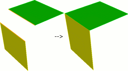
When creating mid-surface geometry it is often useful to extend surfaces to form a corner. To handle this specific but common case use the tweak corner command.
To tweak a pair of curves to a corner
On the Command Panel, click on Geometry and then Curve.
Click on the Modify action button.
Select Tweak from the drop-down menu.
Enter the appropriate value for Curve ID(s). This can also be done using the Pick Widget function.
Select Corner from the drop-down menu.
Enter the appropriate value for Curve ID. This can also be done using the Pick Widget function.
Click Apply.
tweak curve <id> <id> corner [preview]
Figure 165 shows a typical tweak corner example. Notice that surfaces are extended/trimmed to intersect at a corner.
4.6.4.2 Tweak Remove Topology
The tweak remove topology command removes curves and surface from a model and replaces them with new topology. The reconstruction of the new topology and the stitching of it into the model is done using real solid modeling kernel operations. This command is intended to be used on small curves and surfaces in the model. The command tries to find small curves/surfaces neighboring the specified topology and includes these neighbors in the removal process. Thus, the command can often be used to remove networks of small features just by specifying a single curve or surface.
To use the tweak remove topology operation
On the Command Panel, click on Geometry and then Surface or Curve.
Click on the Modify action button.
Select Tweak from the drop-down menu.
Select Remove Topology from the drop-down menu.
Enter the appropriate value for Surface ID(s) and Curve ID(s). This can also be done using the Pick Widget function.
Enter the appropriate value for Small Curve Size and Backoff Distance.
Click Apply.
Tweak Remove_Topology {Surface <id_range> | Curve <id_range> | Surface <id_range> Curve <id_range>} Small_curve_size <val> Backoff_distance <val>
This command is currently only implemented for ACIS and Catia models.
4.6.4.2.1 Example
reset
set attribute on
import ACIS "test10.sat"
separate body all
set attribute off
Auto_clean Volume 1 Split_narrow_regions Narrow_size 2.2
tweak remove_topology curve 19 small_curve_size .21 backoff 1.5
4.6.4.3 Tweaking Surfaces
The following options of the Tweak Surface command are available. Command syntax and examples follow below.
4.6.4.3.1 Tweaking a Surface Using an Offset
To tweak a surface using offset
On the Command Panel, click on Geometry and then Surface.
Click on the Modify action button.
Select Tweak from the drop-down menu.
Select Offset from the drop-down menu.
Enter the appropriate value for Surface ID(s). This can also be done using the Pick Widget function.
Enter in the appropriate Offset Value.
Click Apply.
Tweak Surface <id_list> Offset <val> [Surface <id_list> Offset <val>] [Surface <id_list> Offset <val> ...] [Keep] [Preview]
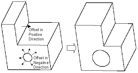
4.6.4.3.2 Tweaking a Surface by Moving
The tweak move form of the command simply moves the given surfaces along a vector direction. The direction can be specified either absolutely or relative to other geometry entities in the model (from entity centroid to location). Note that when moving a surface for tweak, the surface is moved and the surface and the adjoining surfaces are extended or trimmed to match up again. So, for example, moving a vertically oriented planar surface in the vertical direction will have no effect. In this example, if you move the surface 10 in the x and 5 in the y the effect will be to move it simply 10 in the x. You can also use this form of the command to move a protrusion around - just be sure to specify all of the surfaces on the protrusion for moving. The last form of the command can be used to move a surface along another surface’s normal.
To tweak a surface moving
On the Command Panel, click on Geometry and then Surface.
Click on the Modify action button.
Select Tweak from the drop-down menu.
Select Move Delta Distance, Move Normal to Surface, Move to Entity or Move to Location from the drop-down menu.
Enter in the appropriate settings from this menu.
Click Apply.
Tweak Surface <id_range> Move {Vertex|Curve|Surface|Volume|Body} <id> Location {Vertex|Curve|Surface|Volume|Body} <id> [Except [X][Y][Z]] [Keep] [Preview]
Tweak Surface <id_range> Move {Vertex|Curve|Surface|Volume|Body} <id> Location <x_val> <y_val> <z_val> [Except [X][Y][Z]] [Keep][Preview]
Tweak Surface <id_range> Move <dx_val> <dy_val> <dz_val> [Keep] [Preview]
Tweak Surface <id_range> Move Direction <options> Distance <val> [Keep] [Preview]
Tweak Surface <id_range> Move Normal To Surface <id> Distance <val> [Except [X][Y][Z]] [Keep][Preview]
4.6.4.3.3 Tweaking Surfaces to Target Surfaces
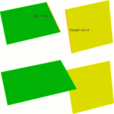
The tweak target form of the command actually replaces the given surfaces with a copy of the new surfaces, then extends and trims surfaces to match up. This can be useful for closing gaps between components or performing more complicated modifications to models. The command syntax is:
To tweak a surface using a target surface
On the Command Panel, click on Geometry and then Surface.
Click on the Modify action button.
Select Tweak from the drop-down menu.
Select Target Surface from the drop-down menu.
Enter the appropriate value for Surface ID(s) and Target Surface ID(s). This can also be done using the Pick Widget function.
Click Apply.
Tweak {Curve|Surface} <id_list> Target {Surface <id_list> [Limit Plane (options)] [EXTEND|noextend] | Plane (options)} [keep] [preview]
Tweak Surface <id_list> Replace [With] Surface <id_list> [Keep] [Preview]
The plane option allows a plane to be specified instead of target surface(s). If a target surface is supplied, the user can also use a limit plane if he wishes. A limit plane is a plane that the tweak will stop at if the tweaked surface does not completely intersect the target surface. The limit plane must be used with the extend option. See the help for Specifying a Plane for the options available to define a plane.
Single target surfaces are automatically extended so that the tweaked body will fully intersect the target. Unfortunately, extending multiple target surfaces can sometimes result in an invalid target, so the option is given to tweak to unextended targets with the noextend option. In this case, the tweaked body must fully intersect the existing targets for success. If you experience a failure when tweaking to multiple targets or the results are unexpected, it is recommended to try the noextend option (NOTE: Tweaking to multiple targets is only implemented in the ACIS geometry engine). It is recommended to always preview before using the tweak target commands.
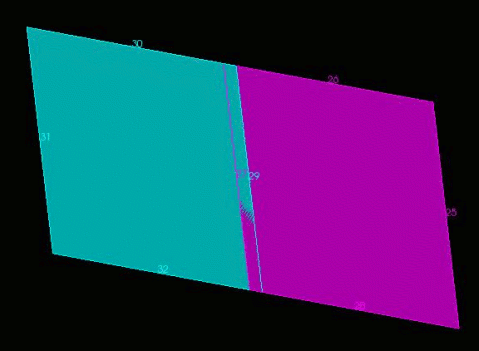
Figure 168 shows a simple example.
Figure 168: Tweak Surface Target (Viewed directly from the side)
4.6.4.3.4 Removing a Surface
The tweak remove command allows you to remove surfaces from a model by extending the adjacent surfaces to fill in the resulting gaps. It is identical to the remove surface command. See Removing Surfaces for a description of the command options.
To remove a surface
On the Command Panel, click on Geometry and then Surface.
Click on the Modify action button.
Select Tweak from the drop-down menu.
Select Remove from the drop-down menu.
Enter the appropriate value for Surface ID(s). This can also be done using the Pick Widget function.
Click Apply.
Tweak Surface <id_list> Remove [EXTEND|Noextend] [Keepsurface] [Keep][Preview]
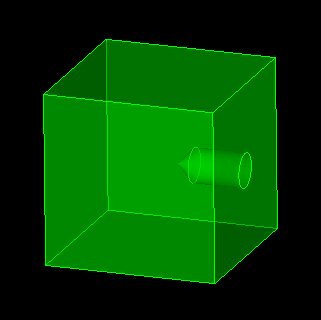
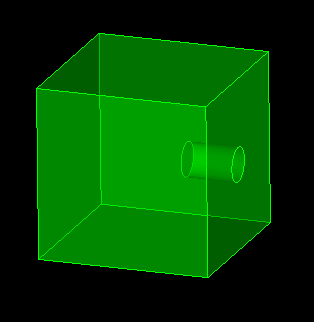
4.6.4.3.5 Tweaking a Conical Surface
The tweak cone form of the command is used to replace a conical projection with a flat circular surface. This command is useful for simplifying bolt holes. The command syntax is.
To tweak a conial surface
On the Command Panel, click on Geometry and then Surface.
Click on the Modify action button.
Select Tweak from the drop-down menu.
Select Cone from the drop-down menu.
Enter the appropriate value for Surface ID(s). This can also be done using the Pick Widget function.
Click Apply.
Tweak Surface <id_range> Cone [Preview]
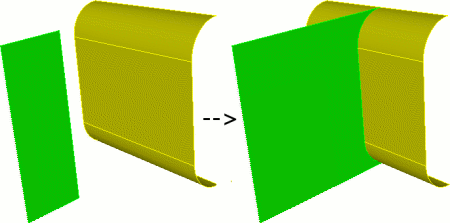
4.6.4.3.6 Tweaking Doublers to Target Surfaces
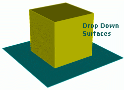
The Tweak Doubler form of the command takes a specified surface and creates drop-down surfaces either normal to the doubler surface or by a user specified vector to a target surface. This can be helpful in creating surfaces for weld elements between midsurfaced geometry. The resulting surfaces do not create a bounding volume, and do not imprint themselves onto the target surface. The command syntax is:
To tweak doublers to target surfaces
On the Command Panel, click on Geometry and then Surface.
Click on the Modify action button.
Select Tweak from the drop-down menu.
Select Doubler from the drop-down menu.
Enter the appropriate value for Surface ID(s) and Target Surface ID(s). This can also be done using the Pick Widget function.
Enter in the appropriate values for direction and limit plane. Click on the direction... or limit plane... button, a window will appear to specify settings.
Click Apply.
Tweak Surface <id_list> Doubler Surface <id_list> {[Limit Plane (options)] [EXTEND|noextend]} [Internal] [Direction (options)] [Thickness] [Preview]
The user can also use a limit plane with a target surface. A limit plane is a plane that the tweak will stop at if the tweaked surface does not completely intersect the target surface. If you use the limit plane option, you must also use the extend option. See the help for Specifying a Plane for the options available to define a plane.
Single target surfaces are automatically extended so that the tweaked body will fully intersect the target. Unfortunately, extending multiple target surfaces can sometimes result in an invalid target, so the option is given to tweak to unextended targets with the noextend option. In this case, the tweaked body must fully intersect the existing targets for success. If you experience a failure when tweaking to multiple targets or the results are unexpected, trying the noextend option is recommended.
If the doubler surface has a thickness property value, you can propagate that thickness value to the newly created drop-down surfaces by using the thickness flag.
It is recommended to always preview before using the tweak doubler commands.
This function only works for ACIS geometry.
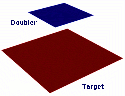
Figure 170: Extending a doubler surface to target geometry (left) and output (right)
The internal option will also include internal curves when the surface is extended (see Figure 171c). The direction option will create a skewed surface along the given direction (see Figure 171d).
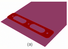
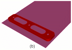
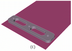
Figure 171: Explanation of tweak doubler options (a) Original surfaces (b) No option flags used (c) Internal option used - notice internal curves dropped down (d) Direction flag - notice skew
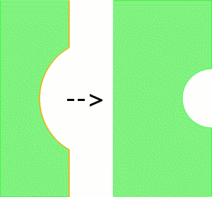
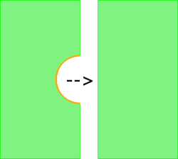
4.6.4.3.7 Removing Holes and Slots from Sheet Bodies
The tweak hole/slot idealize command takes a specified sheet body(s) and searches for either holes or slots (or both) which meet the user’s input parameters. This can be helpful in removing small holes or slots quickly and efficiently from midsurfaced bodies where such level of detail isn’t required. The command syntax is:
To remove holes and slots from sheet bodies
On the Command Panel, click on Geometry and then Surface.
Click on the Modify action button.
Select Tweak from the drop-down menu.
Select Idealize/Remove from the drop-down menu.
Enter the appropriate value for Surface ID(s). This can also be done using the Pick Widget function.
Select Holes or Slots from the Select Feature to Idealize menu.
Enter in the appropriate settings from this menu.
Click Apply.
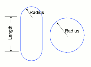
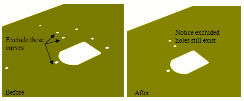
Tweak Surface <id_list> Idealize {[Hole Radius <val>] [Slot Radius <val> Length <val>]} [Exclude Curve <id_list>] [Preview]
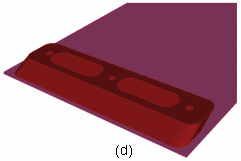
Figure 172: Input parameters for tweak surface idealize command
4.6.4.3.7.1 Hole Removal Example
tweak surface 13 idealize hole radius 6
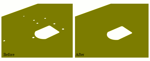
This feature is for ACIS geometry
It is recommended to always preview before using the tweak command. Preview will highlight all curves slated to be removed if the command is executed.
4.6.4.3.8 Removing Fillets from Sheet Bodies
The tweak fillet idealize command takes a specified sheet body(s) and searches for either internal or external fillets (or both) which meet the users’ radius parameter. This can be helpful in removing fillets quickly and efficiently from midsurfaced bodies where such level of detail isn’t required. The command syntax is:
To remove fillets from sheet bodies
On the Command Panel, click on Geometry and then Surface.
Click on the Modify action button.
Select Tweak from the drop-down menu.
Select Idealize/Remove from the drop-down menu.
Enter the appropriate value for Surface ID(s). This can also be done using the Pick Widget function.
Select Fillets from the Select Feature to Idealize menu.
Enter in the appropriate settings from this menu.
Click Apply.
Tweak Surface <id_list> Idealize Fillet Radius <val> {[Internal] [External]} [Exclude Curve <id_list>] [Preview]
4.6.4.3.8.1 Fillet Removal Example
tweak surface 13 idealize fillet radius 6 internal
This feature is for ACIS geometry
It is recommended to always preview before using the tweak command. Preview will show the result if the command is executed.
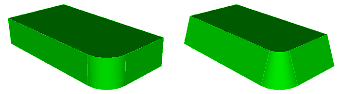
4.6.4.3.9 Changing the Taper of Surfaces
The taper or angle of a surface can be made shallower or steeper using the taper surface command. Several surfaces can be tapered at once to get a smooth transition. The command syntax is:
taper Surface <id_list> angle <val> {from plane <options> | about curve <id> | about vertex <id_1><id_2>} [keep] [preview]
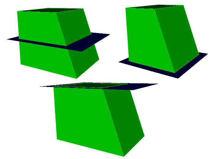
The from plane form of the command is the most basic form of the command. The plane normal defines the direction used to set the angle for the surface. The origin of the plane determines how a surface is tapered. If the plane intersects the middle of a surface, the surface will be rotated in on the top and out on the bottom. If it intersects the bottom, the top of the surface will be rotated in and the bottom will stay fixed. If it intersects the top, the bottom of the surface will rotate out and the top will stay fixed.
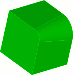
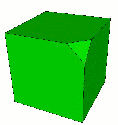
Figure 178: A cube with one surface tapered 20 degrees with a plane in the middle, bottom, and top.
The about curve form of the command can be used to rotate a surface about a curve. The axis of rotation is determined using the tangent direction of the curve at its starting point. That axis crossed with the normal of the surface at the starting point determine the direction used to set the surface angle. In order to work, the curve must be part of one of the surfaces being changed. Since the direction is based on the curve sense, the final direction is not always obvious. Running the command with the preview option first can help determine what angle to apply.
The about vertex form of the command is similar to the about curve form. The axis of rotation is a vector from the first vertex to the second. That axis crossed with the normal of the surface at the starting point determine the direction used to set the surface angle. In order to work, the vertices must be part of one of the surfaces being changed.
4.6.4.4 Tweaking Vertices
This section details the Tweak Vertex command.
4.6.4.4.1 Tweaking a Vertex With a Chamfer
To tweak a vertex with a simple chamfer
On the Command Panel, click on Geometry and then Vertex.
Click on the Modify action button.
Select Tweak from the drop-down menu.
Enter the appropriate values for Vertex ID(s). This can also be done using the Pick Widget function.
Select Simple Chamfer from the drop-down menu.
Enter the appropriate value for Radius Value.
Click Apply.
Tweak Vertex <id_range> Chamfer Radius <value>[Keep] [Preview]
This form of the command creates a chamfered corner at the specified vertex. Can be use on volumes or free surfaces. The ’keep’ option creates another volume on which the tweak is applied; the original volume remains unmodified.
4.6.4.4.2 Tweaking a Vertex With a Non-Equal Chamfer
To tweak a vertex with a complex chamfer
On the Command Panel, click on Geometry and then Vertex.
Click on the Modify action button.
Select Tweak from the drop-down menu.
Enter the appropriate values for Vertex ID(s). This can also be done using the Pick Widget function.
Select Complex Chamfer from the drop-down menu.
Enter the appropriate values for Chamfer Radius 1, Chamfer Radius 2 and Chamfer Radius 3.
Enter the appropriate values for each Along Curve.
Click Apply.
Tweak Vertex <id_range> Chamfer Radius <value> [Curve <id> Radius <value> Curve <id> Radius <value> Curve <id>] [Keep] [Preview]
4.6.4.4.3 Tweaking a Vertex With a Fillet Radius
To tweak a vertex with a fillet vertex
On the Command Panel, click on Geometry and then Vertex.
Click on the Modify action button.
Select Tweak from the drop-down menu.
Enter the appropriate values for Vertex ID(s). This can also be done using the Pick Widget function.
Select Fillet Radius from the drop-down menu.
Enter the appropriate value for Radius Value.
Click Apply.
Tweak Vertex <id_range> Fillet Radius <value> [Keep] [Preview]
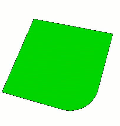
This command replaces a vertex with a filleted radius. The command can only be used on free surfaces. The ’keep’ option creates another volume on which the tweak is applied; the original free surface remains unmodified.
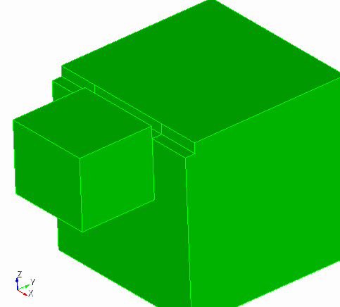
4.6.4.5 Tweak Volume Bend
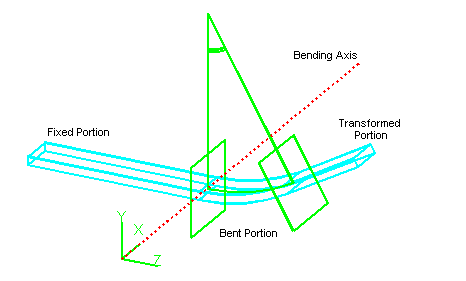
Entity bending bends a solid model around a given axis. In any bending operation, some material is stretched while other material is compressed, but the topology of the model is maintained. The command syntax is:
Tweak {Volume|Body} <id_list> Bend Root <location_options> Axis <direction_vector> Direction <direction_vector> Radius <val> angle <val> [Preview] [Keep] [Center_bend] [Location <options>]
root and axis determine location for the bend. direction determines direction of the bend. radius and angle determine how much to bend. center_bend will bend both sides of the volume around the bend location instead of one side. location can be used to select only specific parts of a volume to bend.
4.6.4.5.1 Example
Bend parts of a body specified by the location option.
create brick width 11 height 1 create brick width 1 depth 10 height 10 create brick width 1 depth 10 height 10 create brick width 1 depth 10 height 10 move body 2 general location position -3 5 0 move body 3 general location position 0 5 0 move body 4 general location position 3 5 0 subtract body 2 from body 1 subtract body 3 from body 1 subtract body 4 from body 1 tweak volume 1 bend root 0 0 0 axis 1 0 0 direction 0 0 -1 radius 1 angle 3.14 location vertex 39 47
4.6.5 Debugging Geometry
Geomdebug Validate [compare] <entity_list>
Consistent CoFace senses
Loops are closed/complete
Consistent CoEdge senses
Correct vertex order on curves w.r.t. parameterization
Correct tangent direction of curves w.r.t. parameterization
4.6.5.1 Related Commands
Geomdebug Vertex <vertex_id>
Geomdebug Curve <curve_id>
Geomdebug Surface <surface_id>
Geomdebug body <body_id>
Geomdebug Containment {Curve | Surface} <id> {Location (options) | Node <id_list>}
Geomdebug Geometry <entity_list> [interval <n>] [index <n>] [TEXT] [GRAPHIC] [attributes]
Geomdebug solidmodel <entity_list> [index <n>] [depth<n>|up<n>|down<n>]
Geomdebug GPE <entity_list>
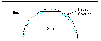
4.6.6 Finding Surface Overlap
Find [Surface] Overlap [{Body|Surface|Volume} <id_list> [Filter_Sliver]
The filter_sliver option will remove false positives from the list by weeding out sliver surfaces that have a merged curve between them. The following pictures is an example of a sliver surface.
4.6.6.1 Facetted Representation
This command works entirely off of the facetted surface representation of the model (the facetted representation is what you see in a shaded view in the graphics). There are inherent advantages and disadvantages with this method. The biggest advantage is avoidance of closest-point calculations with NURBS based geometry, which tends to be slow. This method also eliminates possible problems with unhealed ACIS geometry. The disadvantage is working with a less accurate (i.e., facetted) representation of the geometry. To circumvent problems with this facetted geometry, various settings can be used to control the algorithm. For example, you might consider using a more accurate facetted representation of the model - see below.
4.6.6.2 Find Overlap Settings
Find [Surface] Overlap Settings
4.6.6.2.1 Facet - Absolute/Angle
set overlap [facet] {angle|absolute} <value>
4.6.6.2.2 Gap - Minimum/Maximum
Set Overlap {Minimum|Maximum} Gap <value>
4.6.6.2.3 Angle - Minimum/Maximum
Set Overlap {Minimum|Maximum} Angle <value>
4.6.6.2.4 Normal
Set Overlap Normal {ANY|opposite|same}
4.6.6.2.5 Tolerance
Set Overlap Tolerance <value>
4.6.6.2.6 Group
Set Overlap Group {on|OFF}
4.6.6.2.7 List
Set Overlap List {ON|off}
4.6.6.2.8 Display
Set Overlap Display {ON|off}
4.6.6.2.9 Body
set overlap [within] {body|volume} {on|OFF}
4.6.6.2.10 Imprint
set overlap imprint {on|OFF}
4.6.7 Geometry Accuracy
[set] Geometry Accuracy <value = 1e-6>
Be sure to set it back to 1e-6 before exporting the model or doing other operations as a higher setting can corrupt your geometry
4.6.8 Regularizing Geometry
Regularize Body|Group|Volume|Surface|Curve|Vertex <range>
Set Boolean Regularize [ON | off]
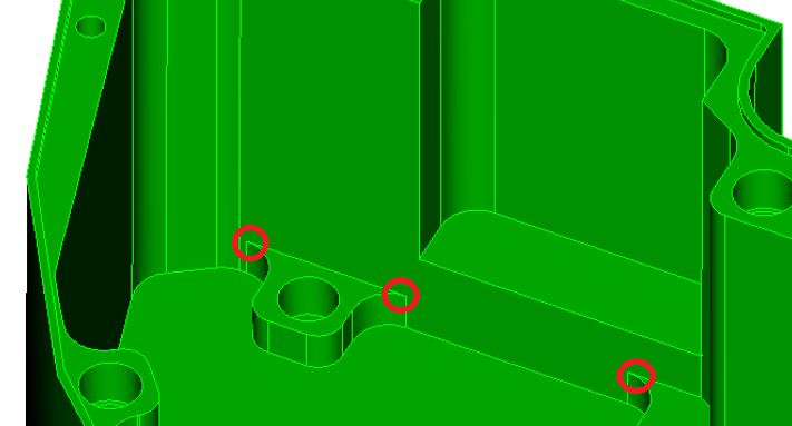
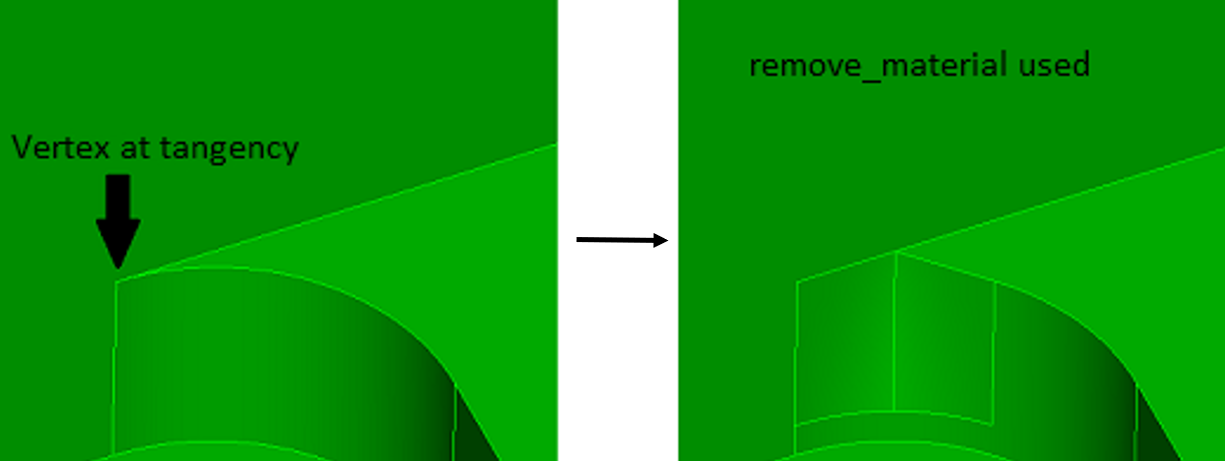
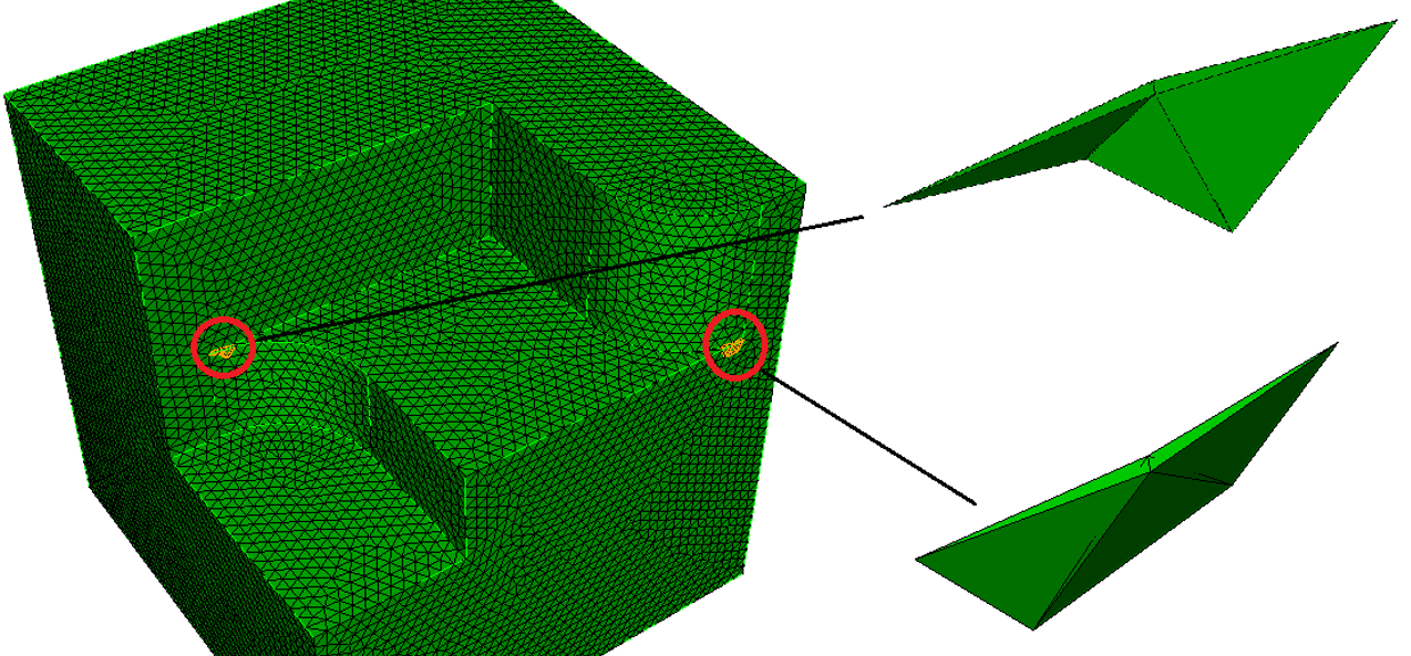
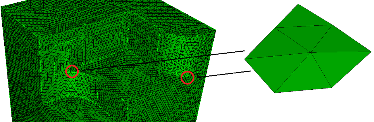
4.6.9 Removing Blunt Tangencies
Removing blunt tangencies will improve the tet-meshability of a volume. Blunt tangencies are caused by fillets and will produce small elements and small timesteps. The operation cuts out the surfaces adjacent to the specified vertex and replaces them with other surfaces that wash over and eliminate the small angle.
blunt tangency vertex <id> [remove_material] [angle <degress=45>] [depth <value>] [preview]
The command panel is shown below in Figure 184. It is a vertex modification operation.
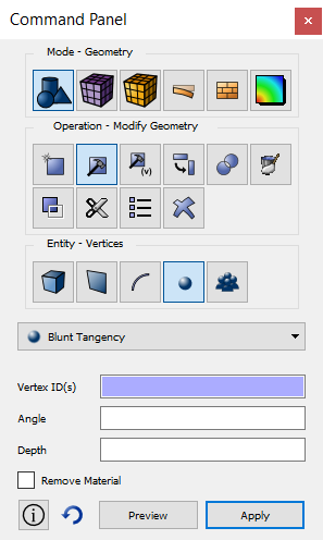
4.6.9.1 Explanation of command parameters
Vertex ID - indicate the ID of the tangency’s vertex
Depth - controls the depth of the surfaces that replace the tangency
Angle - the desired angle at the vertex after the blunt tangency operation. In other words, this controls the extent of the ’blunting’. The default value is 45.0.
Remove_Material - To add material, do not include this parameter. The example in Figure 186 does not remove material. The example in Figure 187 shows the same command when remove_material used.
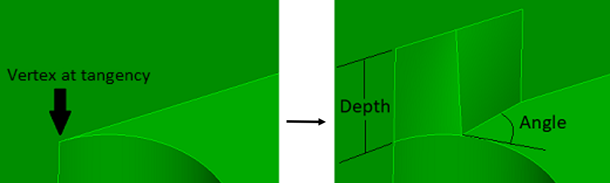
4.6.9.2 Before and after using the command
In this example, the tetmesh produced elements with a minimum scaled Jacobian of approximately 0.0318.
4.6.10 Stitching Sheet Bodies
The stitch command stitches together the specified sheet bodies into either a larger sheet body or a solid volume(s). The tolerance value can be used when these sheet bodies don’t line up exactly along the edges. This is common for IGES and STEP models. Only manifold stitching is performed, i.e., edges will be shared with no more than two surfaces.
To stitch specified sheet bodies together
On the Command Panel, click on Geometry and then Volume.
Click on the Modify action button.
Select Stitch from the drop-down menu.
Enter in the appropriate values for Volume ID(s). This can also be done using the Pick Widget function.
Enter in the appropriate value for tolerancevalue.
Click Apply.
Stitch {Body|Volume} <id_range> [Tolerance <value>] [no_simplify] [No_tighten_gaps]
This command has three stages to it:
Stitch the surfaces together along overlapping edges Normally IGES and some STEP files do not contain topological information that links surfaces together to share bounding curves. Stitching is an operation that builds up this topological information.
Simplify geometry The command replaces splines with analytics where possible.
Tighten up gaps (inaccuracies) between the sheet bodies The command will build the geometry necessary to tighten the gaps in the model.
When the stitch operation completes, a print statement lets the user know if the resulting body is not a closed, solid body.
The user can choose to omit the second and third options of stitching with the no_simplify and no_tighten_gaps options respectively. This may be necessary in very large or complex models, where the regular approach fails, or takes an inordinate amount of time.
4.6.11 Trimming and Extending Curves
To trim or extend curves
On the Command Panel, click on Geometry and then Curve.
Click on the Modify action button.
Select Trim from the drop-down menu.
Enter in the appropriate values for Volume ID(s). This can also be done using the Pick Widget function.
Select Curve or Vertex from the Trim At menu.
Enter in the appropriate settings for this menu.
Click Apply.
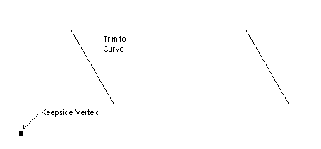
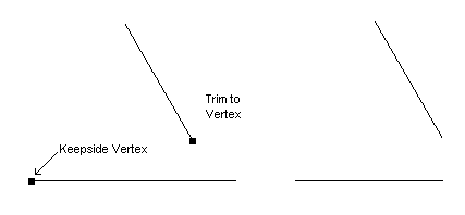
Trim Curve <id> AtIntersection {Curve|Vertex <id>} Keepside Vertex <id> [near]
Curves can be trimmed or extended where they intersect with another curve or at a vertex location. When trimming to another curve, the curves must physically intersect unless they both are straight lines in which case the near option is available. With the near option the closest intersection point is used to the other line - so it is possible to trim to a curve that lies in a different plane. When trimming to a vertex, if the vertex does not lie on the curve, it is projected to the closest location on the curve or an extension of the curve if possible.
The keepside vertex is needed to determine which side of the curve to keep and which side to throw away. This vertex need not be one of the curve’s vertices, nor does it need to lie on the curve. However, if it is not on the curve it will be projected to the curve and that location will determine which side of the curve to keep.
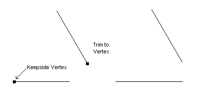
If the curve is part of a body or surface, it is simply copied first before trimming/extending. If it is a free curve a new curve is created and the old curve is removed. The figures below show several examples of trimming/extending curves.
4.6.11.1 Trimming a Curve
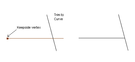
Figure 191: Trimming a Curve to a Non-Intersecting Curve Using the Near Option
4.6.11.2 Extending a Curve
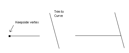
Figure 194: Extending a Curve to a Non-Intersecting Vertex Using the Near Option
4.6.12 Validating Geometry
To validate the geometry and topology
On the Command Panel, click on Geometry.
Click on Volume, Surface, Curve or Vertex.
Click on the Modify action button.
Select Validate from the drop-down menu.
Enter in the appropriate values for Volume ID(s), Surface ID(s), Curve ID(s) or Vertex ID(s). This can also be done using the Pick Widget function.
Enter in the appropriate settings for the Validation/check level.
Click Apply.
Validate {Body|Volume|Surface|Curve|Vertex|Group} <id_range>
Validate {Volume|Surface|Curve|Vertex} <range> Mesh
The validate {...} mesh command performs a connectivity check of the mesh elements to determine the validity of the mesh.
set AcisOption Integer ’check_level’ <integer>
10 = Fast error checks
20 = Level 10 checks plus slower error checks (default)
30 = Level 20 checks plus D-Cubed curve and surface checks
40 = Level 30 checks plus fast warning checks
50 = Level 40 checks plus slower warning checks
60 = Level 50 checks plus slow edge convexity change point checks
70 = Level 60 checks plus face/face intersection checks
set AcisOption Integer ’check_output’ on
That some of the ids listed in the output of the validate command are currently meaningless, e.g. those for coedges.
Validate [Body] <body_id> Normal [Reference [Surface] <surface_id>] [Reverse]
Using the reference keyword, a reference surface is compared to the normal consistency of all other specified surfaces. Inconsistent surfaces can be reversed using the reverse keyword.