4.5 Geometry Decomposition
Geometry decomposition is often required to generate an all-hexahedral mesh for three-dimensional solids, as fully automatic all-hex mesh generation of arbitrary solids is not yet possible in Cubit. While geometry booleans can be used for decomposition (and are the basis of the underlying implementation of advanced decomposition tools described here), Cubit has a webcut capability specially tuned for decomposition. It is also useful to split periodic surfaces to facilitate quad and hex meshing.
4.5.1 Splitting Geometry
The Split command divides curves or surfaces into multiple entities. The command results are similar to imprinting. However, vertex and/or curve creation is not necessary for the split command.
4.5.1.1 Split Curve
The Split Curve command will split a curve without the need for geometry creation (unlike imprinting).
To split a curve
On the Command Panel, click on Geometry and then Curve.
Click on the Modify action button.
Select Split from the drop-down menu.
Enter the appropriate value for Curve ID. This can also be done using the Pick Widget function.
Select Fraction, Vertex ID, By Location, Distance or Pick from the Split Method/Location menu.
Click Apply.
Split Curve <id> [location on curve options] [Merge] [Preview]
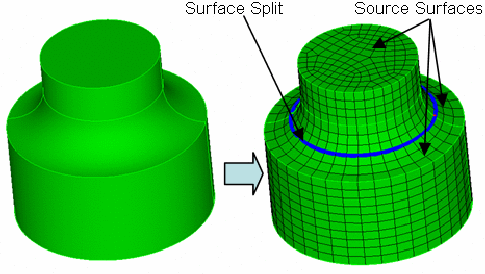
4.5.1.2 Split Periodic Surfaces
Solids which contain periodic surfaces include cylinders, torii and spheres. Splitting periodic surfaces can in some cases simplify meshing, and will result in curves and surfaces being added to the volume.
To split periodic surfaces
On the Command Panel, click on Geometry and then Volume.
Click on the Modify action button.
Select Split Periodic from the drop-down menu.
Enter the appropriate value for Volume ID(s). This can also be done using the Pick Widget function.
Click Apply.
Split Periodic Body <id_range|all>
4.5.1.3 Split Surface
The Split Surface command divides one or more surfaces into multiple surfaces. The command results are similar to imprint with curve. However, curve creation is not necessary for splitting surfaces. Three primary forms of the command are available.
The first form splits a single surface using locations while the second splits by extending a surface hard-line until it hits a surface boundary. The split automatic splits either a single surface or a chain of surfaces in an automatic fashion.
4.5.1.3.1 Split Across
Two forms of Split Across are available
On the Command Panel, click on Geometry and then Surface.
Click on the Modify action button.
Select Split from the drop-down menu.
Select By Location from the drop-down menu.
Enter in the appropriate value for Surface ID(s). This can also be done using the Pick Widget function.
Enter in the appropriate settings on this menu.
Click Apply.
Split Surface <id> Across [Pair] Location <options multiple locs> [Preview [Create]]
Split Surface <id> Across Location <multiple locs> Onto Curve <id> [Preview] Create]]
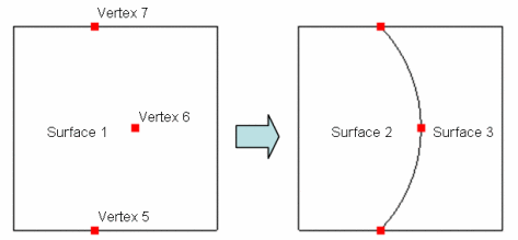
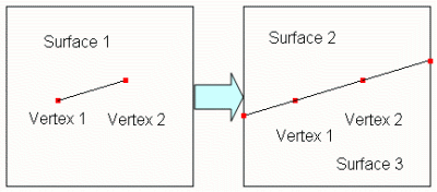
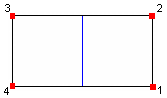
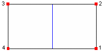
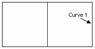
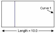
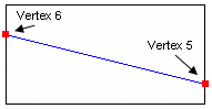
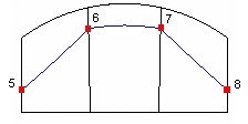
This command splits a surface with a spline projection through multiple locations on the surface. See Location, Direction, and Axis Specification for a detailed description of the location specifier.Figure 136 shows a simple example of splitting a single surface into two surfaces.A temporary spline was created through the three specified locations (Vertex 5 6 7), and this curve was used to split the surface.
split surface 1 across location vertex 5 6 7
split surface 1 across pair vertex 5 7 6 8
The preview keyword will show a graphics preview of the splitting curve.If the create keywordis also specified, a free curve (or curves) will be created - these are the internal curves that are used to imprint the surfaces.
split surface 1 across vertex 5 6 onto curve 4
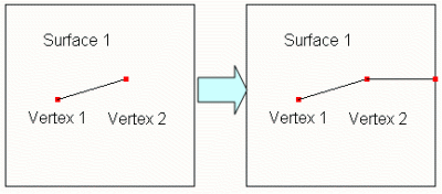
4.5.1.3.2 Split Extend
Split Surface <id_list> Extend [Vertex <id_list> | AUTO] [Preview [Create]]
Set Split Surface Extend Normal {on|OFF}
Set Split Surface Extend Gap Threshold <val>
Set Split Surface Extend Tolerance<val>
split surface 1 extend vertex 2
The auto keyword will search for all hard-lines and extend them according to the Split Surface Extend settings. Figure 140 shows an example:
split surface 1 extend auto
The preview keyword will show a graphics preview of the splitting curve. If the create keyword is also specified, a free curve (or curves) will be created - these are the internal curves that are used to imprint the surfaces.
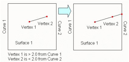
The normal setting can be turned on or off. When it is on, Cubit will attempt to extend the hard-line so that it is normal to the curve it will intersect. An example of this is in Figure 141:
set split surface normal on
split surface 1 extend vertex 2
This setting only applies when using the keyword auto.
set split surface gap threshold 2.0
split surface 1 extend auto
Figure 142: Extending Hard-lines with Gap Threshold = 2.0.
(Notice Vertex 1 was not extended because it exceeded the gap threshold)
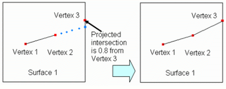
The tolerance setting can be used to avoid creating short curves on the surface boundary. If Cubit tries to extend a hard-line that comes within tolerance of a vertex, it will instead snap the extension to the existing vertex. An example of this is shown in Figure 143:
set split surface tolerance 1.0
split surface 1 extend vertex 2
4.5.1.3.3 Split (Automatically)
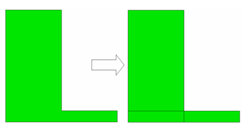
This form of the command splits a single surface or a chain of surfaces in an automatic fashion.It is most convenient for splitting a fillet or set of fillets down the middle - oftentimes necessary to prepare for mesh sweeping. These surfaces cannot have multiple curve loops.
To Split a surface
On the Command Panel, click on Geometry and then Surface.
Click on the Modify action button.
Select Split from the drop-down menu.
Select Along Fillet from the drop-down menu.
Enter in the appropriate value for Surface ID(s). This can also be done using the Pick Widget function.
Click Apply.
Split Surface <id_list>[Corner Vertex <id_list>] [Direction Curve <id>] [Segment|Fraction|Distance <val> [From Curve <id>]] [Through Vertex <id_list>] [Parametric <on|OFF>] [Tolerance <val>] [Preview [Create]]
Each surface is always split with a single curve along the length of the surface (or multiple single curves if the Segment option is used). The splitting curve will either be a spline, arc or straight line.
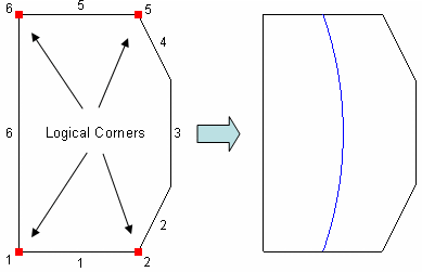
4.5.1.3.3.1 Logical Rectangle
The split will always occur along the chain.
|
|
|
|
|
|
|
|
|
|
|
|
|
|
|
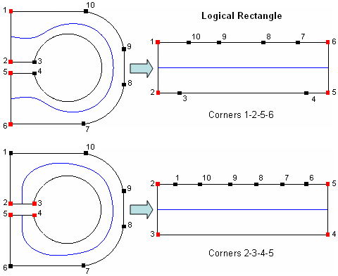
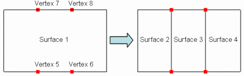
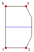
Table 2 shows various surfaces and the resultant split based on the automatically detected or selected logical rectangle. Note that surfaces are always traversed in a counterclockwise direction.
|
|
| |
| |
| |
| |
| |
| |
| |
| |
| |
| |
| |
|

4.5.1.3.3.2 Split Orientation
If a chain of surfaces are split, the surfaces will always be split along the chain. The command will not allow disconnected surfaces.
For a single surface, the split direction logic is a bit more complicated. If no options are specified, the surface aspect ratio determines the split direction - the surface will be split parallel to the longest aspect ratio side through the midpoint of each curve. This behavior can be overridden by the order the Corner vertices are selected (the split always starts on the side between the first two corners selected), the Direction option, the From Curve option, or the Through Vertex list.
Table 3 shows examples of the various split orientation methods. These options are explained in more detail in the sections below.
|
|
| |
| |
| |
| |
| |
|
4.5.1.3.3.3 Corner Specification
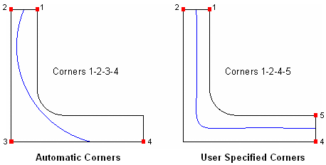
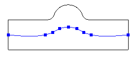
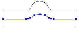
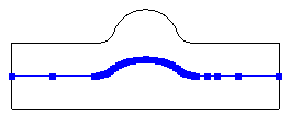
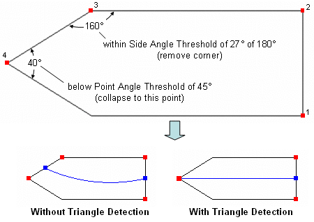
The split can be directed to the tip of a triangular shaped surface by selecting that corner vertex twice (at the start or end of the corner list) when specifying corners, creating a zero-length side on the logical rectangle. A shortcut exists whereas if you specify only 3 corner vertices, the zero-length side will be directed to the first corner selected. If you specify only 2 corner vertices, a zero-length side will be directed to both the first and second corner you select. Table 4 shows these examples. Note the software will automatically detect triangle corners based on angle criteria - the corner selection methods for zero-length sides explained in this section need only be applied if the angles are outside of the thresholds specified in the Set Split Surface Auto Detect Triangle settings.
|
|
| |
|
4.5.1.3.3.4 Direction
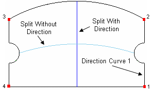
4.5.1.3.3.5 Segment|Fraction|Distance
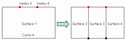
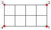
The segment option allows you to split a surface into 2 or more segments that are equally spaced across the surface. The fraction option allows you to override the default 0.5 fractional split location. The distance option allows you to specify the split location as an absolute distance rather than a fraction. By specifying a from curve, you can indicate which side of the logical rectangle to base the segment, fraction or distance from (versus a random result). Table 5 gives examples of these options.
|
|
| |
| |
|
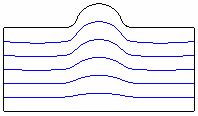
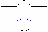
4.5.1.3.3.6 Through Vertex
The through vertex option forces the split through vertices on surface boundaries perpendicularto the splitdirection.Use this option if the desired fraction is not constant from one end of the surface to another or if a split would otherwise pass very close to an existing curve end resulting in a short curve.Through vertices can be used in conjunction with the Fraction option- the split will linearly adjust to pass exactly through the specified vertices.It is not valid with the Segment option.The maximum number of Through Vertices that can be specified is equal to the number of surfaces being split plus one.The selected vertices can be free, but must lie on the perpendicular curves.Table 6 gives several examples. Table 6 - Through Vertex Examples
|
|
| |
|
4.5.1.3.3.7 Parametric
By default, split locations are calculated in 3D space and projected to the surface. As an alternative, split locations can be calculated directly in the surface parametric space. In rare instances, this can result in a smoother or more desirable split. The command option parametric {on|off} can be used to split the given surfaces in parametric space. Alternatively, the default can be overridden with the Set Split Surface Parametric {on|OFF} command.
4.5.1.3.3.8 Tolerance
A single absolute tolerance value is used to determine the accuracy of the split curves. A smaller tolerance will force more points to be interpolated. The tolerance is also used when detecting an analytical curve (e.g., an arc or straight line) versus a spline. A looser tolerance will result in more analytical curves. The default tolerance is 1.0. The command option tolerance <val> can be used to split the given surfaces using the given tolerance. Alternatively, the default tolerance can be overridden with the Set Split Surface Tolerance <val> command.
It is recommended to use the largest tolerance possible to increase the number of analytical curves and reduce the number of points on splines, resulting in better performance and smaller file sizes. The Preview option displays the interpolated curve points. Table 7 shows the effect of the tolerance for a simple example.
|
|
| |
| |
| |
|
4.5.1.3.3.9 Preview
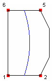
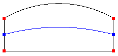
The preview keyword will show a graphics preview (in blue) of the splitting curve (or curves) and the corner vertices (in red) selected for the logical rectangle. The curve preview includes the interpolated point locations that define spline curves. Note that if no points are shown on the interior of the curve, it means that the curve is an analytical curve (line or arc). If the create keyword is also specified, a free curve (or curves) will be created - these are the internal curves that are used to imprint the surfaces. Table 8 shows some examples.
|
|
| |
|

4.5.1.3.3.10 Settings
Set Split Surface Tolerance <val>
Set Split Surface Parametric {on|OFF}
Set Split Surface Auto Detect Triangle {ON|off}
Set Split Surface Point Angle Threshold <val>
Set Split Surface Side Angle Threshold <val>
4.5.1.3.4 Split Skew
Split Surface <id_list> Skew [Preview] [Create]
split surface 1 skew
The preview keyword will show a graphics preview of the splitting curves. If the create keyword is also specified, free curves will be created.
4.5.2 Web Cutting
The term "web cutting" refers to the act of cutting an existing body or bodies, referred to as the "blank", into two or more pieces through the use of some form of cutting tool, or "tool". The two primary types of cutting tools available in Cubit are surfaces (either pre-existing surfaces in the model or infinite or semi-infinite surfaces defined for web cutting), or pre-existing bodies.
The various forms of the web cut command can be classified by the type of tool used for cutting. These forms are described below, starting with the simplest type of tool and progressing to more complex types.
4.5.2.1 General Notes
The primary purpose of web cutting is to make an existing model meshable with the hex meshing algorithms available in Cubit. While web cutting can also be used to build the initial geometric model, the implementation and command interface to web cutting have been designed to serve its primary purpose. Several important things to remember about web cutting are as follows:
The geometric model should be checked for integrity (using imprinting and merging) before starting the decomposition process. This makes the checking process easier, since there are fewer bodies and surfaces to check. Once the model passes that initial integrity check, it is rare that decompositions using web cut will result in a model that does not also pass the same checks.
The use of the Imprint option can in cases save execution time, since it limits the scope of the imprint operations and thereby works faster. The alternative is performing and Imprint All on the pieces of the model after all decompositions have been completed; this operation has been made much faster in more current releases of Cubit, but will still take a noticeable amount of time for complicated models.
While the web cut commands make it very simple to cut your model into very many pieces, we recommend that the user restrict the decomposition they perform to only that necessary for meshability or for obtaining an acceptable mesh. Having more volumes in the model may simplify individual volumes, but may not always result in a higher quality mesh; it will always increase the run time and complexity of the meshing task.
When the web cut command is executed the associated geometry will be regularized. This behavior can be changed, see geometry booleans.
Web cutting volumes will automatically separate parent bodies as well. This behavior can also be changed, see Separating Multi-Volume Bodies.
If a geometric entity got split after the webcut operation, then the notesets/sidesets/blocks applied on that initial geometric entity will be carried over to the split entities.
The Decomposition Tutorials and the Power Tools Tutorial contain some examples that demonstrate the use of web cutting operations.
4.5.2.2 Web Cutting with an Arbitrary Surface
An arbitrary "sheet" surface can also be used to web cut a body. This sheet need not be planar, and can be bounded or infinite. The following commands are used:
To webcut using a sheet
On the Command Panel, click on Geometry and then Volume.
Click on the Webcut action button.
Select Surface Extended from the drop-down menu.
Enter in the appropriate values for Body ID(s) and With Surface ID(s). This can also be done using the Pick Widget function.
Click Apply.
Webcut {blank} with sheet {body|surface} <id> [webcut_options]
Webcut {blank} with sheet extended [from] surface <id> [webcut_options]
Extended sheet surfaces can also be used; in this case, the specified surface will be extended in all directions possible. Note that some spline surfaces are limited in extent, and so these surfaces may or may not completely cut the blank.
4.5.2.3 Chop Command
Chop [Volume|BODY] <id> with [Volume|BODY] <id> [keep] [nonreg]
4.5.2.4 Web Cutting with a Planar or Cylindrical Surface
This section details the commands used to web cut with a planar or cylindrical surface.
4.5.2.4.1 Coordinate Plane
In the command’s simplest form, a coordinate plane can be used to cut the model, and can optionally be offset a positive or negative distance from its position at the origin.
To use a coordinate plane to webcut
On the Command Panel, click on Geometry and then Volume.
Click on the Webcut action button.
Select Coordinate Plane from the drop-down menu.
Enter the appropriate values for Body ID(s). This can also be done using the Pick Widget tool.
Select YZ, ZX or XY.
Enter in the Offset Value.
Enter any other appropriate settings from this menu.
Click Apply.
Webcut {Volume|Body|Group} <id_range> [With] Plane {xplane|yplane|zplane} [Offset <val>] [rotate <theta> about x|y|z <xval> <yval> <zval> [center <xval> <yval> <zval>]] webcut_options
4.5.2.4.2 Planar Surface
An existing planar surface can also be used to cut the model; in this case, the surface is identified by its ID as the cutting tool.
To use an existing planar surface to webcut
On the Command Panel, click on Geometry and then Volume.
Click on the Webcut action button.
Select General Plane from the drop-down menu.
Enter the appropriate values for Body ID(s). This can also be done using the Pick Widget tool.
Enter the appropriate settings for With Plane. By clicking the With Plane... button, another window appears to specify settings.
Enter any other appropriate settings from this menu.
Click Apply.
Webcut {Volume|Body|Group} <id_range> [With] Plane Surface <surface_id> webcut_options
4.5.2.4.3 Plane from 3 Points
Any arbitrary planar surface can be used by specifying three vertices that define the plane, and can optionally be offset a positive or negative distance from this plane.
To use a planar surface by specifying three vertices
On the Command Panel, click on Geometry and then Volume.
Click on the Webcut action button.
Select Plane From Vertices from the drop-down menu.
Enter the appropriate values for Body ID(s), Vertex 1 ID, Vertex 2 ID and Vertex 3 ID. This can also be done using the Pick Widget tool.
Click Apply.
Webcut {Volume|Body|Group} <id_range> [With] Plane Vertex <vertex_1> [Vertex] <vertex_2> [Vertex] <vertex_3> [Offset <value>] webcut_options
4.5.2.4.4 Plane Normal to Curve
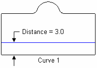
The next command allows a user to specify an infinite cutting plane by specifying a location on a curve. The cutting plane is created such that it is normal to the curve tangent at the specified location.
To specify the cutting plane by specifying the location on the curve
On the Command Panel, click on Geometry and then Volume.
Click on the Webcut action button.
Select Plane From Curve from the drop-down menu.
Enter the appropriate values for Body ID(s) and Curve ID. This can also be done using the Pick Widget tool.
Select Fraction, Position, Distance or Near Vertex from the Position menu.
Enter any other appropriate settings from this menu.
Click Apply.
Webcut {Volume|Body|Group} <id_range> [With] Plane Normal To Curve <curve_id>
{Position <xval><yval><zval> | Close_To Vertex <vertex_id>} webcut_options
Webcut {Volume|Body|Group} <id_range> [With] Plane Normal To Curve <curve_id>
{Fraction <f> | Distance <d>} [[From] Vertex <vertex_id>] webcut_options
A fraction along the curve from the start of the curve, or optionally, from a specified vertex on the curve.
A distance along the curve from the start of the curve, or optionally, from a specified vertex on the curve.
An xyz position that is moved to the closest point on the given curve.
The position of a vertex that is moved to the closest point on the given curve.
The point on the curve can be previewed with the Draw Location On Curve command and the plane to be used for the web cut can be previewed with the preview option in the general webcut options.
4.5.2.4.5 General Plane Specification
A webcut plane can be defined using the general plane specification options in the Specifying a Plane section of the documentation.
To webcut using general plane specification
On the Command Panel, click on Geometry and then Volume.
Click on the Webcut action button.
Select General Plane from the drop-down menu.
Enter the appropriate values for Body ID(s). This can also be done using the Pick Widget tool.
Enter the appropriate settings for With Plane. Click on the With Plane... button, another window appears to specify settings.
Enter any other appropriate settings from this menu.
Click Apply.
Webcut {Volume|Body|Group} <id_range> [With] General Plane {options} webcut_options
4.5.2.4.6 Cylindrical Surface
Finally, a semi-infinite cylindrical surface can be used by specifying the cylinder radius, and the cylinder axis. The axis is specified as a line corresponding to a coordinate axis, the normal to a specified surface, two arbitrary points, or an arbitrary point and the origin. The "center" point through which the cylinder axis passes can also be specified.
To use a cylindrical surface to webcut
On the Command Panel, click on Geometry and then Volume.
Click on the Webcut action button.
Select Cylinder from the drop-down menu.
Enter the appropriate values for Body ID(s). This can also be done using the Pick Widget tool.
Select Value or From Existing Arc from the Radius menu.
Enter in the appropriate values for Radius or Arc ID.
Select X Axis, Y Axis, Z Axis, Vector, Vertex Pair or Surface Normal from the Axis menu.Enter any other appropriate settings from this menu.
Click Apply.
Webcut {Volume|Body|Group} <range> [With] Cylinder Radius <val> Axis {x|y|z|normal of surface <id>| vertex <id_1> vertex <id_2>| <x_val> <y_val> <z_val>>} [center <x_val> <y_val> <z_val>] webcut_options
4.5.2.4.7 Cone Surface
A semi-infinite cone surface can be used by specifying the cone outer radius, and the cone inner radius. The axis is specified as a location first of where the outer radius is applied and the second location of where the inner radius is applied.
On the Command Panel, click on Geometry and then Volume.
Click on the Webcut action button.
Select Cone from the drop-down menu.
Enter the appropriate values for Body ID(s). This can also be done using the Pick Widget tool.
Enter the appropriate values for Radius 1 and Radius 2.
Enter the appropriate settings for Location 1 and Location 2. Click on the Location... button, another window appears to specify settings.
Enter any other appropriate settings from this menu.
Click Apply.
Webcut {Volume|Body|Group} <ids> [With] cone radius <val> <val> location {options} location {options} [Imprint] [Merge] [group_results] [preview]
4.5.2.5 Web Cutting by Sweeping Curves or Surfaces
Webcutting with sweeping creates a swept tool body in the same step as the web cut operation. There are 4 general ways to web cut.
4.5.2.5.1 Web Cutting by Sweeping a Surface Along a Trajectory
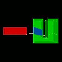
This command allows one or more surfaces to be swept, creating a volume that is used for the web cut. If more than one surface is specified, the surfaces must contain coincident curves. The surfaces are swept along a direction and some distance or perpendicular and some distance or along a curve. For best results the curve to sweep the surface along should intersect one of the surfaces. The through_all option will sweep the surfaces along the trajectory far enough so as to intersect all input bodies. The stop surface <id> option is used to identify a surface at which the sweep will stop. If using this option when sweeping along a curve, the sweep will stop at the first place possible. The up_to_next option indicates that the user wants to web cut with only the first water tight volume that forms as a result of the intersection between sweep and union of all blank bodies. The [outward|inward] options specify a sweeping direction that is either INTO the volume or OUT from the volume.
To sweep a surfvace along a curve or vector
On the Command Panel, click on Geometry and then Volume.
Click on the Webcut action button.
Select Sweep Surface from the drop-down menu.
Enter in the appropriate values for Body ID(s) and Surface ID. This can also be done using the Pick Widget function.
Select Vector or Along Curve from the Direction menu.
Enter in the appropriate settings from this menu.
Click Apply.
Webcut {Volume|Body|Group} <range> Sweep Surface <id_range> {Vector <x> <y> <z> [Distance <distance>] | Along Curve <id>} [Through_all | Stop Surface <id> | Up_to_next ] [webcut_options]
On the Command Panel, click on Geometry and then Volume.
Click on the Webcut action button.
Select Sweep Surface from the drop-down menu.
Enter in the appropriate values for Body ID(s) and Surface ID. This can also be done using the Pick Widget function.
Select Perpendicular from the Direction menu.
Enter in the appropriate settings from this menu.
Click Apply.
Webcut {Volume|Body|Group} <id> Sweep Surface <id_range> Perpendicular {Distance <distance> | Through_all | Stop Surface <id>} [OUTWARD|Inward] [webcut_options]
Figure 151: Example of web cutting with swept surfaces in a direction (left) and result web cut (right)
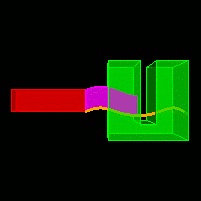
Figure 152: Example of web cutting along a curve to a stop surface (left) and result web cut (right)
4.5.2.5.2 Web Cutting by Sweeping a Surface About an Axis
This command allows one or more surfaces to be swept, creating a volume that is used for the web cut. If more than one surface is specified, the surfaces must contain coincident curves. The surface is swept about a user-defined axis or about one of the x y z coordinate axes and a specified angle. The stop surface <id> option is used to identify a surface at which the sweep will stop. The up_to_next option indicates that the user wants to web cut with only the first water tight volume that forms as a result of the intersection between sweep and union of all blank bodies. For these 2 options to work correctly the user must specify an angle large enough for the rotation to traverse the stop surface or the up_to_next surface.
To sweep a surface by rotating about an axis
On the Command Panel, click on Geometry and then Volume.
Click on the Webcut action button.
Select Sweep Surface from the drop-down menu.
Enter in the appropriate values for Body ID(s) and Surface ID. This can also be done using the Pick Widget function.
Select Rotate About Axis from the Direction menu.
Enter in the appropriate settings from this menu.
Click Apply.
Webcut {Volume|Body|Group} <id> Sweep Surface <id_range> {Axis <xpoint ypoint zpoint xvector yvector zvector> | Xaxis | Yaxis | Zaxis } Angle <degrees> [Stop Surface <id> | Up_to_next] [webcut_options]
4.5.2.5.3 Web Cutting by Sweeping a Curve(s) Along a Trajectory
This command allows a curve(s) to be swept, creating a surface that is used for the web cut. If multiple curves are specified, they must share vertices and form a continuous path. The curve(s) is swept along a direction and some distance or along another curve. If sweeping a curve(s) along another curve, for best results the curve(s)-to-swept and the curve to sweep along should intersect at some point. The stop surface <id> option is used to identify a surface at which the sweep will stop. If using this option when sweeping along a curve, the sweep will stop at the first place possible. The through_all option will sweep the curve(s) along the trajectory far enough so as to intersect all input bodies. For the web cut to be successful, the swept curve(s) must completely traverse a portion of a blank body(s), cutting off a complete piece of the blank body(s). Option through_all should not be used when defining the web cut with a vector and a distance or along a curve.
To sweep a curve along a curve or vector
On the Command Panel, click on Geometry and then Volume.
Click on the Webcut action button.
Select Sweep Curve from the drop-down menu.
Enter in the appropriate values for Body ID(s) and Curve ID. This can also be done using the Pick Widget function.
Select Vector or Along Curve from the Direction menu.
Enter in the appropriate settings from this menu.
Click Apply.
Webcut {Volume|Body|Group} <id> Sweep Curve <id_range> {Vector <x> <y> <z> [Distance <distance>| Along curve <id>] } [Through_all | Stop Surface <id>] [webcut_options]
4.5.2.5.4 Web Cutting by Sweeping a Curve(s) About an Axis
This command allows a curve to be swept, creating a surface that is used for the web cut. If multiple curves are specified, they must share vertices and form a continuous path. The curve(s) is swept about a user-defined axis or about one of the x y z coordinate axes and a specified angle. For the web cut to be successful, the swept curve(s) must completely traverse a portion of a blank body(s), cutting off a complete piece of the blank body(s). The stop surface <id> option is used to identify a surface at which the sweep will stop. For this option to work correctly the user must specify an angle large enough for the rotation to traverse the stop surface.
To sweep a curve about an axis
On the Command Panel, click on Geometry and then Volume.
Click on the Webcut action button.
Select Sweep Curve from the drop-down menu.
Enter in the appropriate values for Body ID(s) and Curve ID. This can also be done using the Pick Widget function.
Select Rotate About Axis from the Direction menu.
Enter in the appropriate settings from this menu.
Click Apply.
Webcut {Volume|Body|Group} <id> Sweep Curve <id_range> {Axis <xpoint ypoint zpoint xvector yvector zvector> | Xaxis | Yaxis | Zaxis } Angle <degrees> [Stop Surface <id>] [webcut_options]
4.5.2.6 Web Cutting using a Tool or Sheet Body
Any existing body in the geometric model can be used to cut other bodies; the command to do this is:
To use an existing body to webcut
On the Command Panel, click on Geometry and then Volume.
Click on the Webcut action button.
Select Tool from the drop-down menu.
Enter the appropriate values for Body ID(s). This can also be done using the Pick Widget function.
Click Apply.
Webcut {blank} tool [body] <id> [webcut_options]
Another form of the command cuts the body list with a temporary sheet body formed from the curve loop. This is the same sheet as would be created from the command Create Surface Curve <id_list>.
To webcut with the body formed from the curve loop
On the Command Panel, click on Geometry and then Volume.
Click on the Webcut action button.
Select Loop from the drop-down menu.
Enter the appropriate values for Body ID(s) and With Curve ID(s). This can also be done using the Pick Widget function.
Click Apply.
Webcut {Body|Group} <id_range> [With] Loop [Curve] <id_range> NOIMPRINT|Imprint] [NOMERGE|Merge] [group_results]
Webcut {Volume|Body|Group} <id_range> [With] Bounding Box {Body|Volume|Surface|Curve|Vertex <id_range>} [Tight] [[Extended] {Percentage|Absolute} <val>] [{X|Width} <val>] [{Y|Height} <val>] [{Z|Depth} <val>]] NOIMPRINT|Imprint] [NOMERGE|Merge] [group_results]
4.5.2.7 Web Cutting Options
The following options can be used with all web cut commands:
[NOIMPRINT|imprint [include_neighbors] ]: In its default implementation, web cutting results in the pieces not being imprinted on one another; this option forces the code to imprint the pieces after web cutting. The include_neighbors option will also imprint adjacent bodies.
[NOMERGE|merge]: By default, the pieces resulting from an imprint are manifold; specifying this option results in a merge check for all surfaces in the pieces resulting from the web cut.
[group_results]: The various pieces resulting from the previous command are placed into a group named ‘webcut_group’.
[preview]: This option will preview the web cutting plane without executing the command.
4.5.3 Section Command
Section {Body|Group} <id_range> [With] {Xplane|Yplane|Zplane} [Offset <value>] [NORMAL|Reverse] [Keep]
Section {Body|Group} <id_range> With Surface <id> [NORMAL|Reverse] [Keep]
4.5.4 Separating Surfaces from Bodies
The separate surface command is used to separate a surface from a sheet body or a solid body.
To separate a surface from a body
On the Command Panel, click on Geometry and then Surface.
Click on the Modify action button.
Select Split from the drop-down menu.
Select Separate from the drop-down menu.
Enter in the appropriate value for Surface ID(s). This can also be done using the Pick Widget function.
Click Apply.
Separate Surface <range>
4.5.5 Separating Multi-Volume Bodies
The separate command is used to separate a body with multiple volumes into a multiple bodies with single volumes.
To separate a body
On the Command Panel, click on Geometry and then Volume.
Click on the Modify action button.
Select Separate from the drop-down menu.
Enter in the appropriate value for Volume ID(s). This can also be done using the Pick Widget function.
Click Apply.
Separate {Body|Volume} <id_range|all>
Set Separate After Webcut [ON|Off]