3.2 Graphical User Interface
The graphical user interface (GUI) can improve user productivity. It provides an easy way to control Cubit without learning command syntax. Many geometry commands are faster and easier with the GUI. The underlying GUI components are constructed using a cross-platform development environment. As such, the GUI will behave similarly across all platforms supported by Cubit, yet each GUI will make use of platform specific widgets. The GUI is built on top of the Cubit command line. This means that GUI actions are translated to a Cubit command-line string and journaled. Users familiar with command-line syntax can enter the same text in the GUI command-line window. Journal files can be created and played back in both environments with the same results. Although many things are faster and easier in the GUI, experienced users often use a combination of command line text and GUI button operations. The discussion of the Graphical User Interface and its features is based on the basic windows contained within the Cubit GUI Application Window. These are outlined in the subtopics listed above.
3.2.1 Coreform Cubit™ Application Window
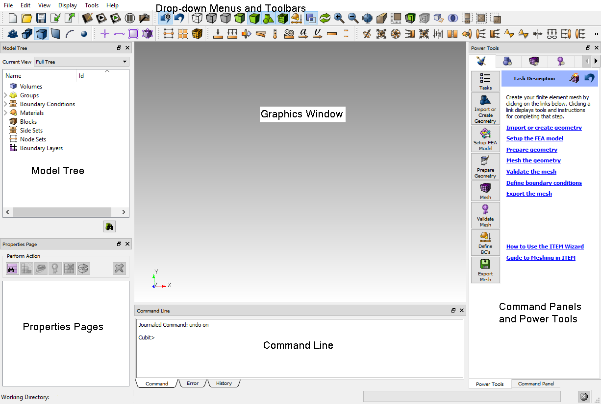
Graphics Window- The current model will be displayed here. Graphical picking and view transformations are done here.
Model Tree - Tree view of the models components, including geometry, materials, boundary conditions, and so forth.
Power Tools - Geometry analysis and repair tool, meshing tool, meshing quality tool, and ITEM Wizard.
Property Editor - The Property Editor lists attributes of the current entity selection. Most of these properties can be edited from the window.
Command Panel - Most Cubit commands are available through the command panels.
Command Line Workspace - The command line workspace contains both the Cubit command and error windows. The command window is used to enter Cubit commands and view the output. The error window is used to view Cubit errors.
Drop Down Menus - Standard file operations, Cubit setup and defaults, display modes, and other functionality is available in the pull-down menus.
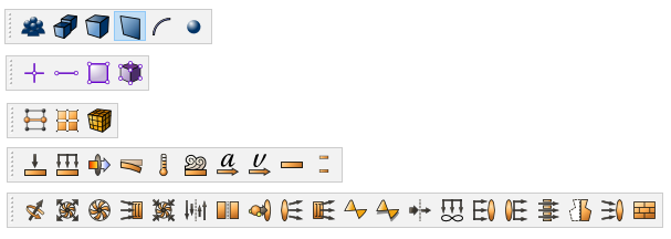
Toolbars - The most commonly used features are available by clicking toolbar icons.
3.2.1.1 Context Sensitive Help in the GUI
The Graphical User Interface has a context-sensitive help system. To obtain help using a specific window or control panel, press F1 when the focus is in the desired window. It may be necessary to click inside a text box to switch focus to a particular window. If no context specific help is available, it will open the Cubit help documentation where you can search for a particular topic.
3.2.1.2 Customizing the Application Window
All windows in the Cubit Application can be Floated or Docked. In the default configuration, all windows are docked. When a window is docked the user can click on the area indicated below.
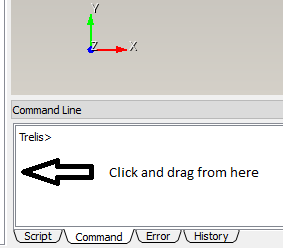
By dragging with the left mouse button held down, the window will be un-docked from the Application Window. Dragging the window to another location on the Application Window and releasing the mouse button will cause it to dock again in a new location. The bounding box of the window will automatically change to fit the dimensions of the window as it is dragged. Releasing the mouse button while the window is not near an edge will cause the window to Float. To stop the window from automatically docking, hold the CONTROL key down while dragging.
When a window is floating, as shown in Figure 14, it is possible to dock it by clicking the title bar of the window and dragging it to its new docked location.
Double clicking on the title bar of an floating window will cause the window to redock in its last docked position.
3.2.2 Command Panels
Geometry Operations
Meshing Operations
Analysis Groups and Materials Operations
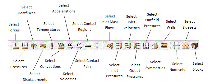
FEA Boundary Condition Operations
CFD Boundary Condition Operations
Post-meshing Launch Control
3.2.2.1 Command Panel Functionality
Use Tools/Options/Command Panels to control these options.
The Command Panel navigation hierarchy can be used in several different ways:
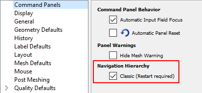
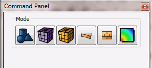
The Classic look includes rows of buttons with icons. The hierarchy is entity-based. Geometric, mesh, and other entity types are the focus of the hierarchy. A user navigates entity types then selects actions to perform on those entities.
The default hierarchy is action-based. Actions such as create, modify, delete, mesh sizing, mesh, boolean, and so forth are the focus of the hierarchy. A user navigates to the action to be performed then selects an entity type on which to perform the action.
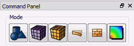
Breadcrumb navigation is new in Cubit 2020.2. The breadcrumb navigation method will use the hierarchy chosen by the user but will present the options in a much more concise manner, freeing up valuable vertical space in the UI. The figures below show the Breadcrumb navigation method.
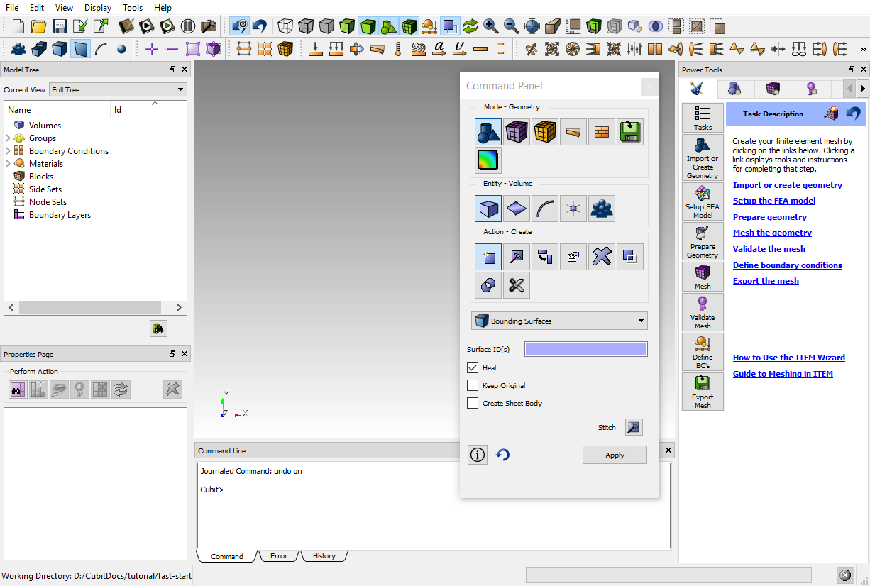
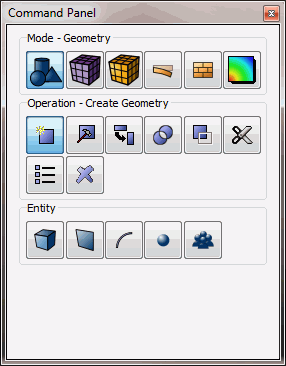
The Command Panel is arranged first by mode on the top row of buttons. Modes are arranged by task. All of the geometry related tasks, for instance, can be found under the Geometry mode. When a mode is selected, a second row of buttons becomes available, then a third. The second row of buttons shown depends on the selected mode.
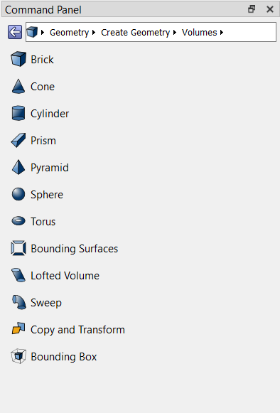
Below is the command panel showing Geometry. Notice the second row shows actions, such as create, modify, transform, boolean, decomposing, and so forth. The third row shows geometry types. This hierarchy implies many geometry operation types are applicable to most entity types.
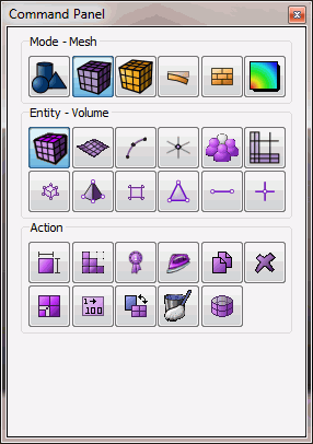
Below is the command panel showing Mesh. Here, the second row shows the various entity types. The third row shows operations that can be performed on those entity types. This hierarchy implies mesh operations tends to be more specific (when compared to geometry operations) to a given mesh entity.
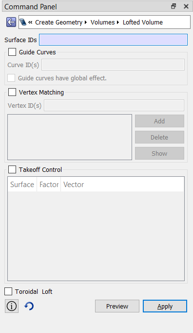
In all cases, regardless of the button hierarchy, the user will finally be presented with a command panel. Shown is the command panel for creating lofted volume.
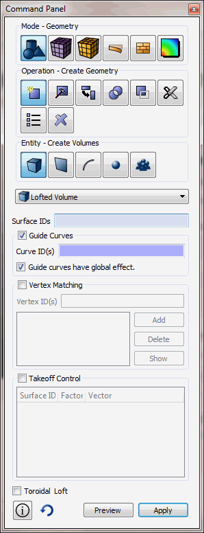
The edit fields are free form, which means the user may enter any valid string into the fields. Any string that is valid for the command line is valid for the command panel edit fields.
3.2.3 Drop Down Menus
The Cubit Drop-Down Menus, located at the top of the Cubit Application Window provide access to capabilities such as file management, checkpoints, display manipulation, journaling, system setup, component management, window management, and help.
3.2.3.1 Cubit (Mac Only)
This menu contains the Preferences dialog box, also called the Options dialog box on other platforms. It also contains the About Cubit menu and the Quit Cubit option. It is only available on Mac computers.
3.2.3.2 File
This menu provides common file operations, including importing and exporting of geometry and meshimport and export. A list of recently saved or imported files is also provided, allowing a quick way to import current or recent work. Non-Mac users can also exit and reset the program from this menu (These options are found under the Cubit tab for Mac Users).
3.2.3.3 Edit
This menu only provides a way to enable the Undo feature of the system. If Undo is enabled, one level of Undo is available to the user.
3.2.3.4 View
The View Menu lists all available toolbars and windows in the current Cubit session. Selecting a toolbar or window will make it visible. Deselecting a toolbar or window will hide it. You can also hide an undocked window or toolbar by clicking on the small "x" in the upper right corner. For more information on docking and undocking toolbars, see Cubit Application Window.}
3.2.3.5 Display
View Point - Controls the camera view point. Choices are front, back, top, bottom, right, left and isometric views.
Render Mode - Controls visibility modes, including: wireframe, true hidden, hidden line, transparent, and shaded.
Geometry - Controls geometry visibility
Mesh - Controls mesh visibility
Graphics Composite - Controls the visibility of composited entities in the graphics window.
Refresh - Updates the graphics display
Background - Changes the background color
Zoom In - Enlarges the model in graphics window
Zoom Out -Shrinks the model in graphics window
Zoom To Fit - Enlarges or shrinks model in the graphics window so it fills the whole screen
Toggle Perspective - When this option is selected, the entities in the graphics display window are drawn in perspective mode.
Toggle Scale - Turns on or off a graphical scale that can be drawn in the graphics window to obtain a bearing on model or part sizes.
Toggle Clipping Plane - Turns on or off the graphics clipping plane
Toggle Clipping Plane Manipulation - Turns on or off manipulation of the graphics clipping plane
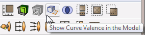
Show Curve Valence - Turns on or off the curve valence highlighting
3.2.3.6 Tools
Journal Editor - Opens journal file editor. The Journal Editor is used to write, edit, play, and save journal files. It can also be used to create and edit Python scripts. A built-in translator will convert between the two files types.
Play Journal File - Plays a specified journal file. You can browse through files and folders on your computer to select the journal file to play.
Options - Opens the Option dialog box. This dialog box controls all of the preferences for the GUI including display colors and widths, mouse settings, journal file options, mesh and geometry defaults, and general layout preferences. MAC users can find this menu under the Cubit tab.
Components - Opens the Components dialog box. This window is used to load and unload external and internal components.
3.2.3.7 Help
Tip of the Day - Open the tip of the day box.
Cubit Tutorials - Opens a menu of step-by-step tutorials for Cubit.
Cubit Manual - Menu to bring up on-line searchable documentation (this document).
About - Menu to show the current version number and trademark information. Mac users can find the version number under the About Cubit menu in the Cubit drop-down.
3.2.4 Options Menu
To change program preferences in the Graphical User Interface select: Tools > Options .
Mac users reach this dialog box by selecting the Cubit > Preferences menu.
3.2.4.1 Command Panels
This menu controls certain behaviors on all command panels.
Automatic Input Field Focus – If checked, when the user clicks the ’Apply’ button to generate a command, input focus will be given to the first field on the command panel.
Automatic Panel Reset – If checked, when the user clicks the ’Apply’ button, the contents of the command panel will be reset to default values.
Hide Mesh Warning – Is a user attempts to mesh an entity that already contains a mesh, a warning will be shown to the user indicating the situation. If this option is checked, the warning will not be shown.
3.2.4.2 Display Preferences
This menu controls entity display features for the graphics window which include the following:
Highlight Surfaces when Highlighting Volume
Set the Graphics Axis to Axis, Origin, or None.
3.2.4.3 General Preferences
This menu controls general program options including the following:
Prompt for Unsaved Application Data - When this is checked and the user opens a new .cub file or exits the application with unsaved changes, a dialog box will pop up asking if they want to save changes first. The user can uncheck this option to prevent that dialog box from appearing. This is checked by default.
Prompt for Unsaved Journal Data - When this button is checked and the user closes the journal file editor with unsaved changes the program will prompt to save the changes. The user can uncheck this button to prevent the dialog box from appearing. It is checked by default.
Change to Script Directory for Playback - When this option is checked, Claro will change the working directory to the directory the script is in when the script/journal file is run. When the script is finished, Claro will change the directory back to the previous one. This is useful when using relative paths in a journal file. When the option is unchecked, Claro won’t change the directory when a journal file is run in which case the user may have to manually change the working directory when their journal file has relative paths.
Prompt When Translating from Python - When checked, if the user translates a python script to a Cubit journal file, the journal editor will warn them that commands may be lost. When unchecked, the journal editor will not issue the warning. There is a checkbox on the warning dialog that sets this option as well.
Default Syntax - Sets the default syntax to use when creating a new journal file in the editor. The Cubit option is only available when the Cubit component is loaded.
Enable Focus Follows Cursor in Command Window – If checked, the focus will be automatically given to the command window when the user moves the cursor into the command window.
Show Startup Splash Screen - Option to hide the startup splash screen on opening Claro.
3.2.4.4 Geometry Defaults
This menu controls the geometry defaults.
Custom Colors for Geometry – The user may specify that all surfaces, curves, and/or vertices are to be colored uniformly.
The user can also change the default geometry engine to one of the following:
The faceting tolerance can also be controlled from this menu to change the way facets are drawn in the graphics window. The default file format may be set.
Cubit (*.Cubit) – HDF5 Cubit files contain the same information stored in Cubit files, that is, geometry, mesh, and mesh containers. In addition, a Cubit file includes the journal file used to create the model. Including the journal file is user-definable. The Cubit file is stored in HDF5 format making it possible for 3rd parties to store related data in the same file without disturbing the operation of Cubit.
Cubit (*.cub)
Mesh Auto Delete
Auto Delete On – When toggled on, will execute the command, "set mesh autodelete on". When toggled off, will execute the command "set mesh autodelete off".
3.2.4.5 History Preferences
This menu controls the input window history and journal file options. These include:
Maximum Number of Commands - The max number of commands kept in the current command history.
Comment Line Filtering - Whether to count comments in command history.
Maximum Number of Lines - Maximum number of lines in input window.
Journal Command History - Whether to use a journal file to save command history. Default is to use a journal file.
Journal File Directory - Where the journal file will be saved. Default is the starting directory.
Journal File Name - The name of the journal file. A name will be given by default if one is not specified. The default name for the GUI version of Cubit is historyxx.jou with xx as the highest used number between 01 and 999 incremented by 1.
3.2.4.5.1 Cubit History Preferences
Use Cubit Journaling - When this option is checked, Cubit journaling will be used. By default it is checked.
Output Log - When this option is checked, you can save error log to a separate output file.
3.2.4.6 Label Defaults
This menu controls the geometry and mesh entity labels in the graphics window.
Label Geometry and Mesh Entities Toggles- Choose label visibility for each type of geometry or mesh entity
3.2.4.7 Layout Preferences
This menu option controls input window formatting and control panel docking options.
Font for command line workspace
Font size for command line workspace
Reset Window Layout Button - Used to reset GUI windows to their default positions
Also included in the layout preferences is a list of available windows with a checkbox to show/hide each window.
3.2.4.7.1 Cubit Layout Settings
This menu controls the layout of Cubit specific buttons and tabs on the GUI.
Toolbars and Docking Windows - Show/hide various toolbars and docking windows.
Show script tab - Shows the script tab on the command line window
Window Tab Position - various Cubit tools are contained in Tabbed windows. The tabs can be shown at the top, bottom, left-side, or right-side of the window.
3.2.4.8 Mesh Defaults
Mesh Line Color - The same as "Color Lines" command.
Default Element Type - Tet/Tri or Hex/Quad
Surface Scheme Coloring (used in Meshing Power Tool) - This option allows you to select different colors for surface schemes when visualized using the meshing power tools.
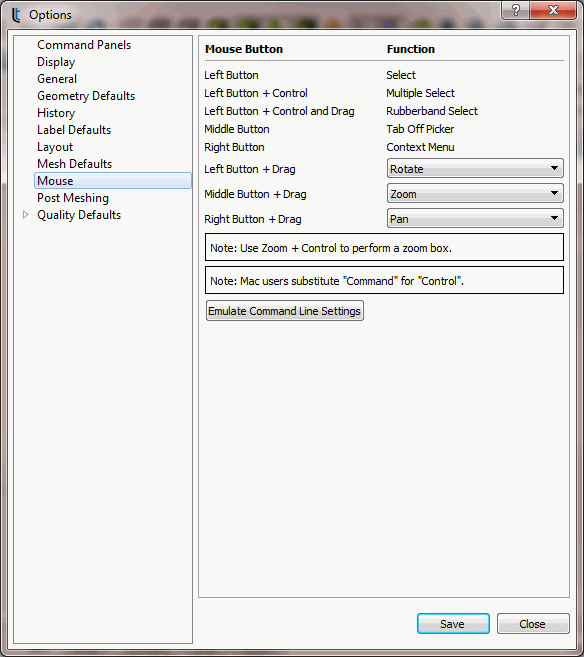
3.2.4.9 Mouse Settings
This menu controls mouse button controls. Pressing the Emulate Command Line Settings button will cause all of the settings to simulate mouse controls in the command line version of Cubit. For a detailed description of mouse settings see the View Navigation-GUI page.
3.2.4.10 Post Meshing Settings
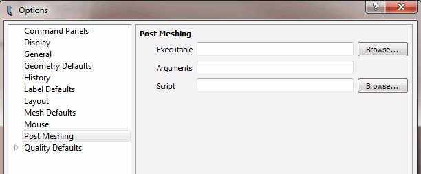
Executable – Specify an executable file to launch when the button is pressed
Arguments – Indicate the arguments that will be passed to the executable
Script – Provide a path to a script (journal file or python script) which will be run BEFORE launching the executable.
3.2.4.11 Quality Defaults
This menu controls quality defaults for different quality metrics. For a description of the different quality metrics see the respective pages:
3.2.5 Undo Button
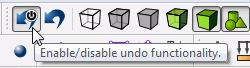
Cubit has an undo capability. To enable the Undo feature click on the Enable Undo button on the Toolbar.
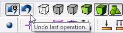
With undo enabled, click the undo button to reverse operations.
Alternatively to turn undo on and off, the following command may be used in the command line:
undo {on|off}
The Undo capability is implemented for geometry and some meshing commands including webcutting, geometry creation, transformations, and booleans. The commands will be undone in reverse order of their execution.
3.2.5.1 Limitations
The undo button is not currently enabled for some meshing commands
3.2.6 Graphics Window
3.2.6.1 Viewing Curve Valence
To view your model based on a color-coded curve valence scale, click on the curve valence button on the Display Toolbar. Curve valence refers to the number of surfaces attached to each curve. Curves with exactly two surfaces attached are shown in blue. Curves with exactly one surface are shown in red. Curves with more than two attached surfaces are shown in white.
3.2.6.2 Selecting Entities in the GUI
3.2.6.2.1 Pre-Selection
When the mouse cursor is over an entity type that has been selected from the Pick toolbar, that entity will become highlighted. This is called pre-selection and is used as a graphical guide to show which entity will be picked when the mouse button is clicked. Graphics pre-selection may slow down your graphics speed for large models. You can disable pre-selection from the Tools->Options dialog box.
3.2.6.2.2 Polygon, Sphere, and Box Select
The polygon/box/sphere selection feature allows you to select entities by drawing a box, sphere or polygon on the screen. To draw a box or sphere on the screen press and hold the <CTRL> button* while clicking and dragging the left mouse button. Release the left mouse to complete the box or sphere select. To create a polygon selection, press and hold the <CTRL>* button while clicking and dragging the left mouse button. Click the left mouse button to create another side for the polygon. Press either of the other buttons to close the polygon and complete the selection. Only entities that are in active selection mode will be selected. To change between the polygon or box method, press the Toggle Between Polygon/Box/Sphere Select button on the Select Toolbar. Clicking the Toggle Selected Enclosed/Extended button will toggle between Enclosed Selection and Extended Selection. Enclosed selection will only select entities that are fully enclosed within the bounding box or polygon. Extended selection will select entities that are either fully OR partially enclosed within the bounding box. Toggling the the Select X-Ray will select entities that are hidden behind other entities. X-ray selection will only apply to smoothshade and hiddenline graphics modes. *Note: For Mac computers use the command (or apple) button for polygon or box select.
3.2.6.3 Key Press Commands for the GUI
Several commands have a key press shortcut. These commands will be executed with respect to the currently selected entities; see the following table:
Shortcut Key | Command |
l | List information about the current entity to the output window. |
i | Toggle the visibility of the selected entity. |
e | Echo entity id to command line |
TAB | Select the next entity. |
SHIFT-TAB | Select the previous entity. |
0 | Toggle picking of vertices. |
1 | Toggle picking of curves. |
2 | Toggle picking of surfaces. |
3 | Toggle picking of volumes. |
4 | Toggle picking of groups. |
SHIFT-0 | Toggle picking of mesh nodes. |
SHIFT-1 | Toggle picking of mesh edges. |
SHIFT-2 | Toggle picking of mesh faces. |
SHIFT-3 | Toggle picking of mesh hexes. |
F5 | Refresh graphics window. |
SHIFT-S | Activate/inactivate graphics clipping plane. |
3.2.6.4 Right Click Commands for the GUI Graphics Window
Clicking the Right mouse button in the graphics window will bring up a menu. One of two menus will appear, depending on whether an entity is currently selected.
3.2.6.4.1 With Entity Selected
When an entity is selected, the options available will depend upon the type of entity selected. The following describes the menu options and when they are available.
3.2.6.4.1.1 Entity Selections
|
|
|
|
|
|
|
|
|
|
|
|
|
|
|
|
|
|
|
|
|
|
|
3.2.6.4.1.2 Entity Visualization
|
|
|
|
| |
|
| |
|
|
|
|
| |
|
| |
|
| |
|
|
|
|
| |
|
|
3.2.6.4.1.3 Entity Operations
|
|
|
|
|
|
|
|
|
|
| |
|
| |
|
| |
|
| |
|
| |
|
| |
|
| |
|
|
3.2.6.4.2 Without Entity Selected
|
|
|
|
| |
|
| |
|
| |
|
| |
|
|
3.2.6.5 View Navigation in the GUI
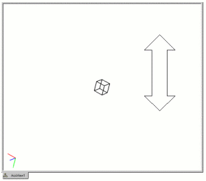
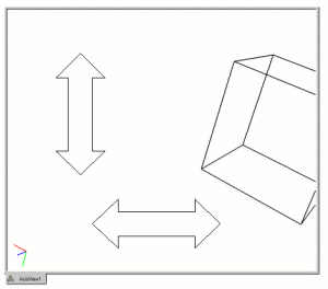
3.2.6.5.1 Rotations
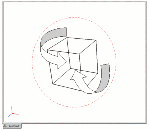
Where the cursor is in the graphics window will dictate how the view will be rotated. If the cursor is outside of an imaginary circle, shown in Figure 30, the view will be rotated in 2d, around an axis normal to the screen. If it is inside the circle, as in Figure 31, the rotations will be in 3d, about the current view spin center. The spin center can be changed to any x-y-z location. The most common way is by zooming to an entity, which changes the spin center to the centroid of that entity. The "view at" command will change the spin center without zooming:
view at vertex 3
Figure 30: With the mouse pointer outside the circle the view is rotated about an axis normal to the screen
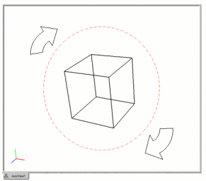
Figure 31: With the mouse pointer inside the circle the view is rotated about the current spin center
3.2.6.5.2 Zooming
3.2.6.5.3 Panning
3.2.7 Tree View
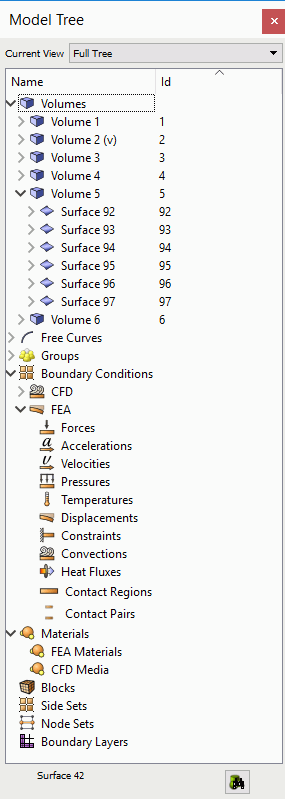
3.2.7.1 Model Tree
3.2.7.1.1 Drag and Drop
The Tree View window supports drag and drop of geometric entities into existing boundary condition sets. To create boundary conditions, see the Materials and Properties menu on the main control panel, or right-click on one of the boundary condition labels and select the "Create New" option from the context menu. Geometric entities or groups can be added to blocks, nodesets, or sidesets by dragging and dropping inside the tree view window.
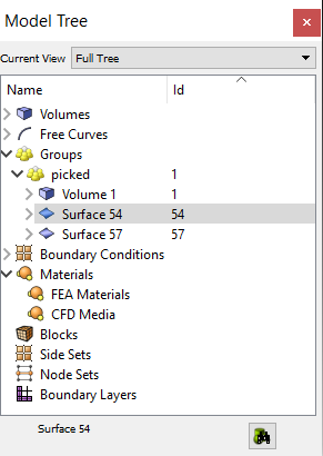
3.2.7.1.2 Picked Group
3.2.7.1.3 Right-Click Menu Functions
The model tree’s context menu is sensitive to the type of item and the number of items selected. Functions that apply to the item type and number of selected items are available from the context menu. These include the following:
Zoom To - Available for all geometric entities
Rotate About - Change the center of rotation to the centroid of the entity without zooming
Fly-In - Animated zoom feature
Locate - Labels the selected entity in the graphics window
Draw - Draw this entity by itself.
Isolate - Similar to Draw command, but the display will not be refreshed with a graphics reset. To redisplay the model, select All Visible from the graphics window right-click menu.
Transparency On/Off - Toggles transparency mode
Visibility On/Off - Toggles visibility
Rename - Allows you to rename entities from the tree. Clicking on a highlighted entity in the tree will do the same thing. This will also work for boundary condition entities (blocks, nodesets and sidesets)
Mesh - Mesh selected entity at current settings.
Delete Mesh - Available for meshed entities
Reset Entity - Deletes mesh, and returns all settings to default values.
Delete - Available when Volumes and Groups are selected.
Refresh Full Tree - Used to return to main tree
Collapse Tree - Available when entities are selected.
View Descendants/Ancestors - Show this entity’s individual hierarchy. Use the Refresh Full Tree option to return to main tree view.
View Neighbors View adjacent entities. Use the Refresh Full Tree option to return to the main tree view.
Create New Volume - Available when the user right-clicks over the Volumes (parent) label. Opens the geometry-volume-create panel
Import Geometry - Available when the user right-clicks over the Volumes (parent) label. Opens import dialog.
Create New Group - Available when the user right-clicks over the Groups (parent) label.
Clean Out Group - Available when groups are selected. Removes all entities from group.
Remove from Group - Available when groups are selected. Removes selected entity from the group.
Add Selected to Block/Nodeset/Sideset - Add the selected entity in the graphics window to the chosen block, nodeset, or sideset in the model tree.
Delete Selected from Block/Nodeset/Sideset - Delete the selected entity in the graphics window from the chosen block, nodeset, or sideset in the model tree.
Create New Block/Sideset/Nodeset - Available when the user right-clicks over the respective Boundary Conditions (parent) label.
Create New <boundary condition> - Available when highlighting desired boundary condition in the tree including CFD and FEA boundary conditions.
Draw Block/Sideset/Nodeset - Draws the selected block/nodeset/sideset on top of existing entities
Draw Sideset/Nodeset Only - Draws the selected nodeset/sideset independent of other entities
Delete Selected Boundary Condition - Deletes any selected boundary conditions
Draw Selected Boundary Condition - Draws selected boundary condition by itself
Draw Selected Boundary Condition (Add) - Draws multiple boundary conditions
List Selected Boundary Condition - Lists information about selected boundary conditions in the command line window
Remove from Block/Sideset/Nodeset - Removes selected entity from the specified block, sideset or nodeset
Cleanup (Tets) - Issues cleanup command for selected block. Only applicable for blocks composed of tet elements
Remesh (Tets) - Issues remesh command for selected block. Only applicable for blocks composed of tet elements
List Info - List information about selected entity in the output window.
3.2.7.2 Power Tools
The power tools contain useful tools to help users through the mesh generation process. A very useful tool for new users is the Immersive Topology Environment for Meshing, also known as ITEM. This panel contains a wizard-like environment which guides the user through the mesh generation process through a series of panels and diagnostics. The geometry tool allows users to create new boundary conditions/assemblies/groups, add entities to existing boundary conditions/assemblies/groups, make entities visible/invisible, and rename entities. The geometry repair and analysis tools contains diagnostics and tools for analyzing and repairing geometry, although many of these can now be found in the ITEM environment as well. The mesh quality and meshing power tools aid in mesh generation and verification. The power tools are presented in the tabbed folder from left to right:
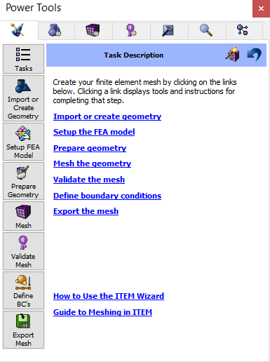
To familiarize yourself with the power tools environment we recommend that you try the power tools tutorial. To familiarize yourself with ITEM wizard we recommend that you try the ITEM tutorial.
3.2.7.3 Geometry Power Tools
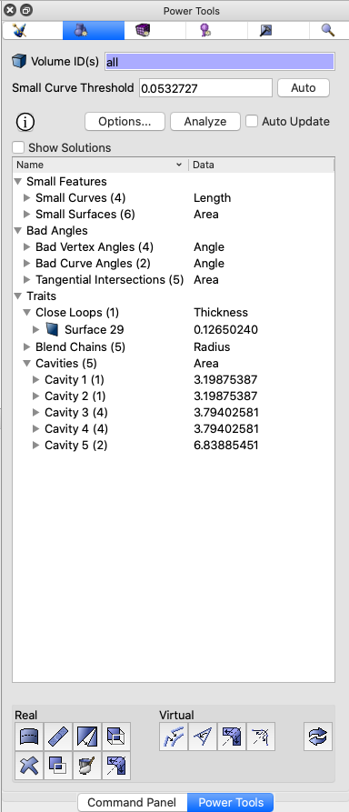
The geometry power tools, shown in Figure 37. are located on the Tree View window under the blue geometry tab. The Geometry Power Tool provides several diagnostic tests to identify and repair problems in your CAD model prior to meshing. Diagnostic tests include:
Small Features: Small curves and surfaces and volumes
Bad Angles: Near tangent angles at curves and vertices
Geometric Traits: Identifies common geometric traits such as holes, blends, chamfers, etc.
Assembly Checks: Gaps, overlaps and misalignments between multiple parts
This tool analyzes geometry for various characteristics that may affect meshing outcomes and aid in simplification and defeaturing. It also contains a powerful toolkit of geometry modification methods to fix these problems. Many of the common geometry clean-up tools are available from this tool without the need to search through the command panels for relevant operations. The geometry power tool includes a window that lists results from geometry analysis in a tree format. In addition, a solution window can be displayed that will display specific suggested geometry solutions for the currently selected entity.
3.2.7.3.1 Suggested Usage
The following is a suggested workflow for using the geometry power tool:
Enter volumes to analyze: Enter or pick the volume IDs you wish to analyze in the field labeled Volume ID(s). By default, all volumes will be analyzed. For large or complex assemblies, consider selecting only a few volumes at a time to avoid long analysis times.
Enter a small curve threshold: The value entered in the field labeled Small Curve Threshold defines the basis for what is considered "small" for most geometry tests. If Cubit already has more than one volume defined, a default value for small curve threshold will be computed as 0.25*mesh_size. To update the default small curve threshold for the current volumes, select the Auto button. If no mesh size is currently defined, an autosize factor of 2.5 will be used to compute a mesh size. (Equivalent to vol all size auto factor 2.5)
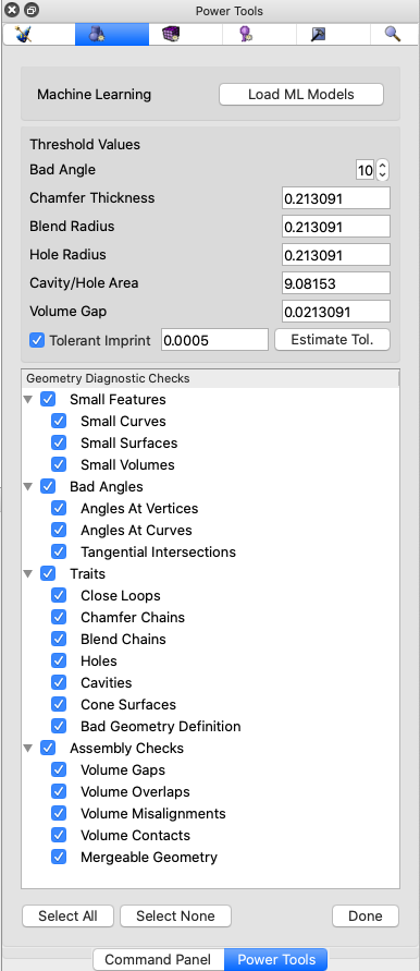
Select diagnostics to perform: Selecting the Options... button will display a list of available diagnostics grouped by category, as shown in Figure 38. By default all diagnostics are selected. Some diagnostics may not apply to specific geometry, or may only need to be run once per geometry. To avoid long analysis times, select only diagnostics that are relevant for your current problem scope. Clicking on the box by each test will select or deselect it. Categories of diagnostics may also be selected or deselected in a similar manner. All diagnostics may be selected or deseleted using the Select All and Select None buttons at the bottom of the panel. Threshold values used for some of the diagnostics can also be entered, including bad angle, chamfer thickness, blend or hole radius, cavity area and volume gap thresholds. Details on each of the diagnostics are described below. Select the Done button to return to the main Geometry power tool panel.
Analyze the geometry: Click the Analyze button to initiate an analysis of the selected diagnostics. The time taken for analysis will vary based on the number and complexity of volumes and the diagnostics selected.
Select an entity to examine: Once analysis is complete, the results will appear in the main window of the geometry power tool panel in the form of an expandable lists categorized by the selected diagnostics. Items in the list correspond to the selected tests. Expanding a list will display an ordered sub-list of geometry entities that have been identified by the test. Selecting one or more entities in one of the lists will also highlight the entities in the graphics window. Use shift-click or command/ctrl-click to select multiple entities in the list. Use the context menu (right click) to zoom or fly in, locate, draw or other methods to graphically examine the selected entities.
Choose a geometry repair solution: Multiple methods are provided for choosing and selecting a relevant geometry repair solution:
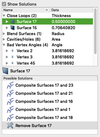
Context Menu: Right clicking on an entity in the list will reveal a list of options that are normally relevant for the selected entity type. (See Figure 39.) For example, selecting the Remove Surface... menu item will bring up the Remove Surface command panel pre-populated with the relevant entity. To execute the same operation on many entities at once, first select all relevant entities in the list.
Show Solutions: Selecting the Show Solutions check box at the top of the results window will display an additional window, (See Figure 40.) populated with relevant operations for the currently selected entity. Selecting a solution will display a preview of the operation in the graphics window. Double clicking the solution will execute the solution. A right click on the solution will show a context menu revealing the following options:
Execute: Execute the selected solution (same as double click).
Show More Solutions: Add additional solutions computed for attached entities if they exist. For example, if a small curve is selected, this option will include additional solutions in the window for its attached surfaces and vertices.
Open Command Panel Operation: Depending on the type of solution selected, the relevant command panel will appear pre-populated with the options called for in the solution. This provides the option to further customize the solution if the precise desired command is not displayed.
Command Panel Buttons: The buttons at the bottom of the geometry power tool will display a specific geometry command panel. This can be useful if many similar operations are to be performed on different entities. A description of each is provided below.
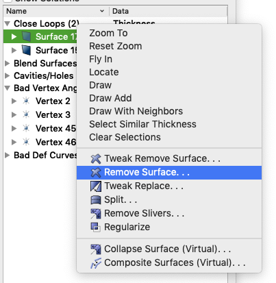
Figure 40: Entity-specific solutions displayed in geometry power tool.
3.2.7.3.2 Geometry Analysis Tools
The geometry power tools, contain various diagnostic tests that can be run on geometry to diagnose potential problems for mesh generation and defeaturing. To display a list of tests, click on the Options... button. The panel shown in Figure 38. will appear. Select or deselect the desired options from the window before performing an analysis. To avoid long analysis times, select only tests that are relevant for your current problem scope. Cubit will also save the current test selections between runs. The geometry analysis tests are summarized below:
3.2.7.3.2.1 Small Features
Small features may be necessary and desirable in a model, but many times they are the result of poor geometry construction, or they may just not be important to the analysis. The small features tests look for small curves, small surfaces, and small volumes. These tests rely on the user-defined small curve threshold value defined at the top of the Geometry poert tool.
Small Curves - Small curves, including zero-length curves such as hardpoints, are compared directly against the small curve threshold value, and identified if they are less than or equal to the given value.
Small Surfaces - Small surfaces are identified based on area and hydraulic radius. Surface areas that are less than the square of the current mesh_size are identified as small. For surfaces where the hydraulic radius, defined as 4*surface_area/perimeter, is less than the small curve threshold are also identified as small.
Small Volumes - Small volumes are identified by their hydraulic radius, defined as 6*volume/surface_area.
3.2.7.3.2.2 Bad Angles
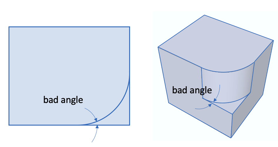
At Vertices - For vertices, the angle formed by two attached curves is measured. Vertices where angles less than the bad angle threshold. Figure 41 shows an example of a bad angle where the resulting tet or hex mesh may result in poor mesh quality. Note that depending on how the angle is measured at the vertex, the small angle may be also be identified if 360.0-angle is less than the bad angle threshold. The blunt tangency or collapse angle operations are useful for removing bad angles at curves.
At Curves - For curves, the angle formed by two attached surfaces is measured. Similar to vertices, curves where angles less than the bad angle threshold are identified.
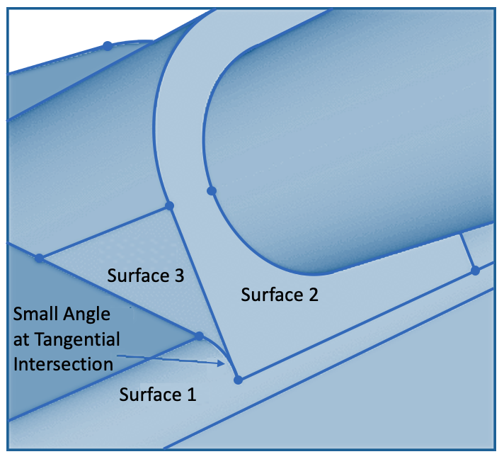
Tangential Intersections - A tangential intersection is formed when two parallel surfaces share an edge and have a 180 degree angle between them. The tangential intersection test is looking for the condition where two surfaces that meet tangentially share a common edge, and each of the surfaces has another edge which resides on a third face and forms a small angle. In the example shown in Figure 42., Surface 1 and Surface 2 are tangential to each other and share a common edge. Both Surface 1 and 2 have another edge which resides on Surface 3 and forms a small angle at the vertex common to all three surfaces.
3.2.7.3.2.3 Traits
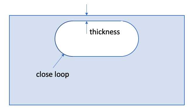
Close Loops - Close loops are identified by two curves on a single surface for which the shortest distance between them is less than the current mesh_size. Surfaces identified as close loops are ordered based on the minimum thickness of the surface between the loops. These surfaces and their immediate neighbors are often candidates for the remove surface command.
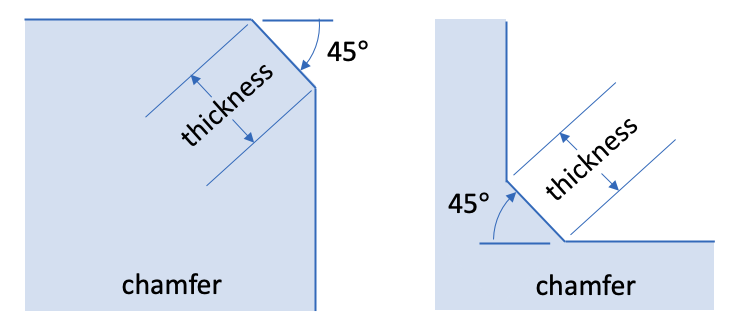
Chamfer Chains - A chamfer surface can be identified as a narrow strip where its angle to neighboring surfaces is about 45 degrees as shown in figure 43. Chamfers often occur as a chain or connected set of surfaces and are grouped together in the power tool as a collection of surfaces that can be expanded and examined individually. Chamfer chains are ordered based on the narrow thickness of the surfaces illustrated in figure 44. Setting the Chamfer Thickness threshold in the Options panel will control which chamfer chains will be identified. The default value for Chamfer Thickness threshold is the current mesh_size Since chamfers with small thickness can effect the resulting size of the elements the remove surface option is often used to eliminate them.
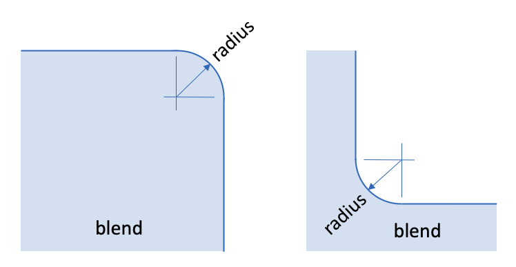
Blend Chains - A blend surface serves as a smooth transition between two neighboring surfaces, such as a fillet as shown in figure 44. Blends are identified as surfaces having a constant radius along one of its parametric directions. Blends often occur as a chain or connected set of surfaces and are displayed as a collection of surfaces in the power tool that can be expanded and examined individually. Enter a Blend Radius threshold value at the top of Geometry power tools options panel to control the maximum radius of curvature for surfaces returned from this test. The default value for blend radius threshold is the current mesh_size. Resulting blend surfaces are ordered based upon their minimum radius of curvature. Blend chains can be candidates for the remove surface blend_chain or split surface commands.
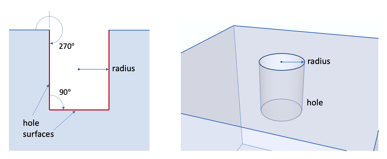
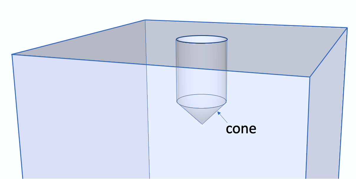
Holes - Holes are a special category of Cavity (see below). They are collections of surfaces that are bounded by curves where the exterior angle is greater than 180 degrees and at least one of the surfaces have a radius of curvature less than the hole radius threshold. Figure 370 illustrates a hole that is comprised of a cylindrical surface and a planar circular surface. Resulting hole collections of surfaces are ordered based upon their cylindrical radius. Holes can be candidates for the remove surface cavity command.
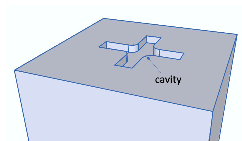
Cavities - Small cavities in a volume may be candidates for removal from the geometry. A cavity is defined as a collection of surfaces bounded by curves with an external angle greater than 180 degrees. Enter the cavity area threshold value at the top of the Geometry power tools Options panel. This value controls the maximum total surface area for a cavity identified from this diagnostic test. Since cavities may consist of many individual surfaces, the resulting ordered list displayed in the power tool includes sub-lists of surfaces that can be expanded and examined individually. Surfaces contained with cavities or holes can be candidates for the remove surface cavity command which will remove all surfaces in the cavity simultaneously.
Cone Surfaces - Cones are defined as any surface comprising exactly two curves where one of the curves is of zero length. Cone surfaces can often cause difficulty for surface meshing, and should be removed when possible. Surfaces identified as cones are ordered based on their surface area. Cone surfaces are good candidates for the tweak surface cone command.
Bad Geometry Definition - Cubit uses third party libraries, such as ACIS from Spatial, Inc. for much of its geometric modeling capabilities. The bad geometry definition check calls internal validation routines in these libraries, when available, to check for errors in geometry definition. Entities identified as "bad geometry" are usually candidates for the heal volume command. If the third party library does not provide validation capabilities, this check will not return anything.
ACIS is a trademark of Spatial.
3.2.7.3.2.4 Assembly Checks
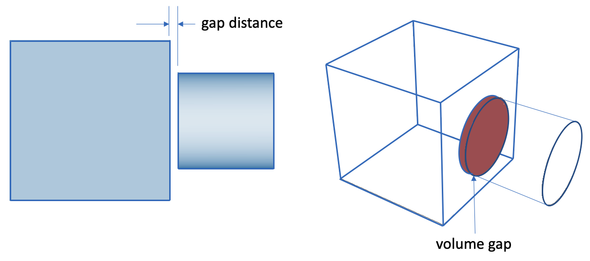
Volume Gaps - Lists volume pairs that are separated by a distance smaller than the volume gap tolerance specified in the Options panel, but are not in contact or overlapping. Gaps can result in parts that are not correctly merged and will not share nodes between volumes when meshed. Expanding a volume pair in the list will display individual surface pairs where gaps exist between the volumes. Figure 373 illustrates a gap between two volumes. Gaps can be visualized using the draw volume gap context menu, also shown in Figure 373, where the surfaces that are within the gap tolerance are displayed in red. The tweak surface replace command can sometimes be used to correct overlaps.
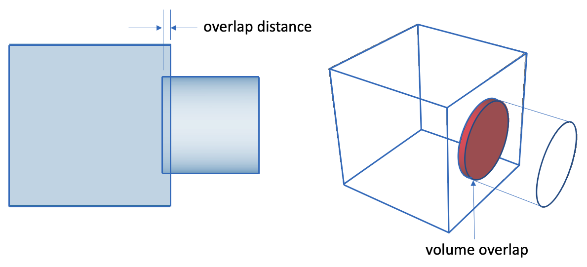
Volume Overlaps - Lists volume pairs that are overlapping. Figure 374. shows an example of a volume overlap. Overlapping volumes can result in sliver surfaces and bad element quality if they are not resolved prior to imprinting and merging. Overlaps can be displayed with the context menu item, draw volume overlap which displays the overlap region in red. The remove overlap command or tweak surface replace commands can often be used to correct overlaps.
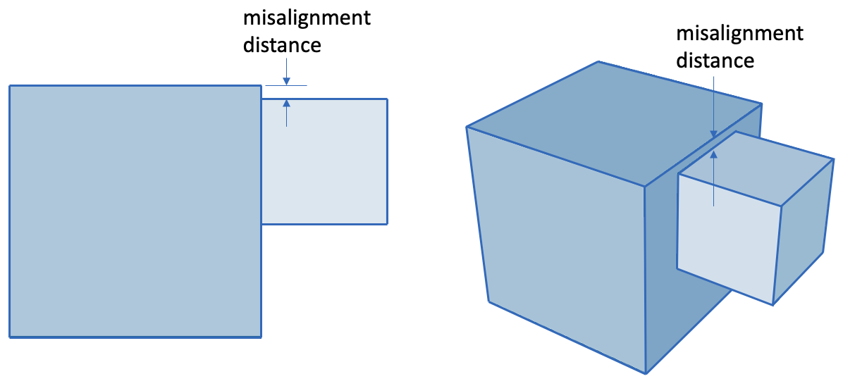
Volume Misalignments - Misalignments are caused when neighboring volumes touch without overlap, but a small distance between neighboring vertices, curves or surfaces is identified. Figure 375 shows an example of a misalignment. Misalignments can result in sliver surfaces and bad element quality if not resolved prior to imprinting and merging. The volume misalignments diagnostic test will list pairs of volumes that are misaligned. Expanding a volume pair will reveal entity to entity misalignments that were detected between the pair. Three categories of misalignments will be displayed, namely: vertex-vertex, vertex-curve and vertex-surface ordered by their misalignment distance. These indicate entity pairs that are closer than the volume gap tolerance that is set in the Options panel. The tweak surface replace command can often be used to correct misalignments.
Volume Contacts - Volumes that have surfaces in contact but not merged are displayed with this diagnostic test. This provides a way to distinguish volumes that are merged from those that are not and validate whether a contact state should exist between neighboring volumes. This list will include volume pairs that are touching including those that have been identified by the volume misalignment diagnostic test. Expanding a volume pair will reveal pairs of surfaces on different volumes that are in contact. If the contact state is not correct, normally an imprint and merge operation should be performed
Mergable Geometry - Pairs of entities on neighboring volumes that are co-located are identified by this diagnostic test. This is normally used to verify that the expected set of surfaces are coincident prior to merging. Mergable geometry pairs of surfaces, curves and vertices are displayed in this list. Lower order entities (ie. curves and vertices) will not be displayed if its parent geometry (ie. surface) is identified as mergable. In most cases, lower order entities identified by this diagnostic indicate the existence of overlaps or misalignments and should be resolved before imprint and merging. Note that the default merge tolerance of 1e-6 is used to determine if entities are mergable unless the tolerant imprint checkbox is selected in the Options panel and a user defined tolerance is set.
3.2.7.3.3 Geometry Repair Tools
The geometry repair tool buttons appear at the bottom of the Geometry Power Tool. Selecting one of these buttons will bring up the relevant command panel. Tools included in this panel have proven useful for geometry repair and defeaturing.
![]() Split Surface Button The split surface tool is used to split a surface into two surfaces. This is useful for blend surfaces, for example, where splitting a surface may facilitate sweeping. To select a surface for splitting, click on the surface in the tree view. To select multiple surfaces in the window, hold the CTRL key* while selecting surfaces (surfaces must be attached to each other). Then press the split surface button to bring up the Control Panel window with the ids of selected surfaces in the text input window. The split surface menu is located on the Control Panel under Geometry-Surface-Modify. You must press the Apply button for the command to be executed. You can also bring up the Split Surface menu by selecting surfaces in the tree view and selecting Split from the right click menu.
Split Surface Button The split surface tool is used to split a surface into two surfaces. This is useful for blend surfaces, for example, where splitting a surface may facilitate sweeping. To select a surface for splitting, click on the surface in the tree view. To select multiple surfaces in the window, hold the CTRL key* while selecting surfaces (surfaces must be attached to each other). Then press the split surface button to bring up the Control Panel window with the ids of selected surfaces in the text input window. The split surface menu is located on the Control Panel under Geometry-Surface-Modify. You must press the Apply button for the command to be executed. You can also bring up the Split Surface menu by selecting surfaces in the tree view and selecting Split from the right click menu.
For Mac computers, use the command key (or apple key) to select multiple entities.
![]() Heal Button The healing function in Cubit is used to improve ACIS geometry that has been corrupted during file import due to differences in tolerances, or inherent limitations in the parent system. These errors may include: geometric errors in entities, gaps between entities, and the absence of connectivity information (topology). To heal a volume, select the volume in the geometry repair tree view. Then press the heal button. You may also press the heal button without a geometry selected in the window, and enter it later. The Control Panel window will come up under the Geometry-Volume-Modify option with the selected volume id highlighted. If no entity is selected, or if another entity type is selected, the input window will be blank. You can also open the healing control panel by selecting Heal from the right click menu in the geometry power tools window.
Heal Button The healing function in Cubit is used to improve ACIS geometry that has been corrupted during file import due to differences in tolerances, or inherent limitations in the parent system. These errors may include: geometric errors in entities, gaps between entities, and the absence of connectivity information (topology). To heal a volume, select the volume in the geometry repair tree view. Then press the heal button. You may also press the heal button without a geometry selected in the window, and enter it later. The Control Panel window will come up under the Geometry-Volume-Modify option with the selected volume id highlighted. If no entity is selected, or if another entity type is selected, the input window will be blank. You can also open the healing control panel by selecting Heal from the right click menu in the geometry power tools window.
Only curves with valence 2 or less at each vertex are candidates for tweaking. Any other curve will cause the Geometry-Surface-Modify menu to appear.
![]() Merge Button The merge command is used to merge coincident surfaces, curves, and vertices into a single entity to ensure that mesh topology is identical at intersections. Unlike other buttons on the geometry repair panel, the merge button acts as an "Apply" button itself. All geometry that is listed under "mergable entities" will be merged.
Merge Button The merge command is used to merge coincident surfaces, curves, and vertices into a single entity to ensure that mesh topology is identical at intersections. Unlike other buttons on the geometry repair panel, the merge button acts as an "Apply" button itself. All geometry that is listed under "mergable entities" will be merged.
![]() Remove Button The remove button is used to simplify geometry by removing unnecessary features. To use the remove feature, click on the surface(s) in the Tree View. Right click and select the Remove Option, or click the Remove icon on the toolbar. The Control Geometry-Surface-Modify control panel will appear, with the surface ids in the input window. The Remove control panel can also be accessed from the right-click menu in the Geometry Power Tools window. Select options and press apply.
Remove Button The remove button is used to simplify geometry by removing unnecessary features. To use the remove feature, click on the surface(s) in the Tree View. Right click and select the Remove Option, or click the Remove icon on the toolbar. The Control Geometry-Surface-Modify control panel will appear, with the surface ids in the input window. The Remove control panel can also be accessed from the right-click menu in the Geometry Power Tools window. Select options and press apply.
![]() Regularize Entity Button The regularize button is used to remove unnecessary topology. Regularizing an entity will essentially undo an imprint command.
Regularize Entity Button The regularize button is used to remove unnecessary topology. Regularizing an entity will essentially undo an imprint command.
![]() Remove Slivers The remove slivers button is used to remove surfaces with less than a specified surface area. When ACIS removes a surface it extends the adjoining surfaces to fill the gap. If it is not possible to extend the surfaces or if the geometry is bad the command will fail.
Remove Slivers The remove slivers button is used to remove surfaces with less than a specified surface area. When ACIS removes a surface it extends the adjoining surfaces to fill the gap. If it is not possible to extend the surfaces or if the geometry is bad the command will fail.
![]() Auto Clean Geometry The auto clean button is used to perform automatic cleanup operations on selected geometry. These automatic cleanup operations include forcing sweepable configurations, automatically removing small curves, automatically removing small surfaces, and automatically splitting surfaces.
Auto Clean Geometry The auto clean button is used to perform automatic cleanup operations on selected geometry. These automatic cleanup operations include forcing sweepable configurations, automatically removing small curves, automatically removing small surfaces, and automatically splitting surfaces.
![]() Composite Button The composite button is used to combine adjacent surfaces or curves together using virtual geometry. Virtual geometry is a geometry module built on top of the ACIS representation. Surfaces may be composited to simplify geometry in order to facilitate sweeping and mapping algorithms by removing constraints on node placement. It is important to note that solid model operations such as webcut, imprint, or booleans, cannot be applied to models that have virtual geometry. Both curves and surfaces may be composited.
Composite Button The composite button is used to combine adjacent surfaces or curves together using virtual geometry. Virtual geometry is a geometry module built on top of the ACIS representation. Surfaces may be composited to simplify geometry in order to facilitate sweeping and mapping algorithms by removing constraints on node placement. It is important to note that solid model operations such as webcut, imprint, or booleans, cannot be applied to models that have virtual geometry. Both curves and surfaces may be composited.
![]() Collapse Angle Button The collapse angle button uses virtual geometry to collapse small angles. This is accomplished by partitioning and compositing surfaces in a way so that the small angle gets merged into a larger angle. Pressing the collapse button on the geometry power tools will open the collapse menu under Geometry-Vertex-Modify control panel. This panel can also be opened by selecting Collapse from the right click menu in the Geometry Tools window.
Collapse Angle Button The collapse angle button uses virtual geometry to collapse small angles. This is accomplished by partitioning and compositing surfaces in a way so that the small angle gets merged into a larger angle. Pressing the collapse button on the geometry power tools will open the collapse menu under Geometry-Vertex-Modify control panel. This panel can also be opened by selecting Collapse from the right click menu in the Geometry Tools window.
![]() Collapse Surface Button Pressing this button will open the collapse surface panel on the main control panel. The collapse surface function uses virtual geometry to eliminate small surfaces on the model to improve mesh quality. It is most useful for blend surfaces.
Collapse Surface Button Pressing this button will open the collapse surface panel on the main control panel. The collapse surface function uses virtual geometry to eliminate small surfaces on the model to improve mesh quality. It is most useful for blend surfaces.
![]() Collapse Curve Button Pressing this button will open the collapse curve panel on the main control panel. The collapse curve command is used to eliminate small curves using virtual geometry.
Collapse Curve Button Pressing this button will open the collapse curve panel on the main control panel. The collapse curve command is used to eliminate small curves using virtual geometry.
Pressing most of the geometry tool buttons on the panel will only bring up applicable command panels on the Control Panel. You must press the Apply button on the Control Panel to execute the command.
3.2.7.3.4 Context (Right Click) Menu
The following right click menu options are available from the geometry power tool’s main window when a geometry entity or category is selected. Figure 39. shows an example of a context menu. Specific options depend on the type of entity or category.
3.2.7.3.4.1 Test Categories
Select All - Selects all entities in the category
Draw All - Draw all entities in the category
Draw All Add - Draw all entities in the category without first clearing the display
Locate All - Labels all entities in the category in the graphics window. Refresh screen to hide.
Expand All - Expand all categories to show sub-lists of entities
Collapse All - Collapse all categories to hide sub-lists of entities
3.2.7.3.4.2 Entity Visualization Options
Zoom To- Zoom to selected entity in the graphics window
Reset Zoom - Reset graphics window zoom
Fly-in - Animated zoom
Locate - Labels the selected entities in the graphics window. Refresh screen to hide.
Draw - Displays only selected entities by themselves.
Draw Add - Adds the selected entity to the display without clearing.
Draw with Neighbors - Displays only selected entities with all attached neighbors
Select Similar ... - Selects other entities in the same category that have the same geometry characteristic. For example, area, loop thickness, blend radius, angle at vertex, etc.
Clear Blend Chain - Available in Blend category. Selects surfaces in the same blend chain as the selected surface.
Clear Cavity/Hole - Available in Cavity/Hole category. Selects surfaces in the same cavity or hole collection as the selected surface.
Clear Selections - Clears all highlighted entities and reset graphics
3.2.7.3.4.3 Cubit Solution Options
Each of the following menu options are available based on the category and entity type selected. In each case they will open the relevant command panel pre-populated with the entity selected. Select multiple entities prior to selecting the context menu item below to execute the command on multiple entities simultaneously.
3.2.7.4 Meshing Tools
The meshing power tool provides a tool for determining whether a geometry can be meshed using autoscheme, or if it requires its scheme to be set explicitly. This tool is designed to help guide users through geometry decomposition process by providing a convenient way to see which geometries need further modification or decomposition prior to meshing.
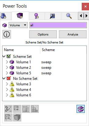
Figure 1. Meshing Power Tools
Entity Specification- The meshing power tool works for volumes or surfaces.
Options Button - Opens the Tools>Options dialog to change the visualization colors of surface schemes for the meshing tool
Analyze Button - The Analyze button issues the autoscheme command for all selected volumes and surfaces.
Output Tree - The output from the meshing tool is displayed in tree format. Geometry is divided into "Scheme Set" and "Scheme Not Set" divisions. The geometry is listed under these nodes. If autoscheme was successful, its assigned scheme is also displayed.
Toggle Visibility Button - The meshing tool displays entities as red or green in the graphics window. Green means that they are currently meshable using the autoscheme. Red means that they require their scheme to be set explicitly. Turning this capability off will return the volumes and surfaces to their original colors.
Meshing Tools Buttons - Several meshing tools are available to the user from this window. Depending on the entity selected, these are also available from the right-click context menu, and they are described below.
3.2.7.4.1 Right Click Context Menu
Zoom To - Zoom in on this element in the graphics window
Draw - Draw this entity by itself in the graphics window
Locate - Locates and labels entity in the graphics window
Rotate About - Issues Rotate about command for selected entity
Visibility On/Off - Toggle visibility
Reset Graphics- Reset graphics display
Set Size - Opens the Mesh/Entity/Interval panel on the control panel where you can set interval sizes for the selected geometry
Set Scheme - Opens the Mesh/Entity/Mesh panel on the control panel where you can set a scheme for the selected entities
Set Vertex Type - Available when surfaces are selected. Opens the Mesh/Surface/Mesh panel to set vertex types.
Imprint/Merge- Opens the Geometry/Entity/Merge panel on the control panel. If you have entities selected in the tree window it will input them to the imprint/merge command.
Webcut - Opens the Geometry/Volume/Webcut panel on the control panel. If a volume is selected in the meshing tool window it will input it in the webcut panel.
Color Surfaces - Color surfaces based on their schemes. You can change the default colors by selecting the Options button.
Restore Colors - Restores colors on selected entity or entity type
Mesh - Meshes the selected entities (bypassing control panel)
Delete Mesh - Deletes the mesh on selected entities
Unmerge - Unmerges selected entities
View Descendants - Opens a list of child entities and their meshing schemes. Press Analyze to return.
View Ancestors- Opens a list of parent entities and their meshing schemes. Press Analyze to return.
View Neighbors- Opens a list of bordering entities and their meshing schemes. Press Analyze to return.
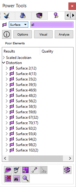
3.2.7.5 Mesh Quality Tools
The mesh quality tool is located in the entity tree window under the quality tab. The Mesh Quality Tool works on meshed entities to analyze mesh quality based on selected metrics. Output from the mesh quality analysis can be visualized using color-coded scales. The mesh quality tool also contains tools to improve mesh quality including smoothing, refinement, node merging, mesh validation, deleting mesh elements, and repositioning nodes.
Help Button - Opens context specific help for this topic.
Options Button - Clicking on this button will show the Tools>Option menu dialog that allows users to manually enter metric range settings. The settings are persistent between sessions. For a description of quality metrics and default ranges click on one of the following links:
Visual Button - Clicking on this button will open the Mesh/Entity/Quality command panel specific to the entity selected. To visualize elements in the graphics window based on a color-coded quality scale, you must select the entities to visualize and check the "Display Graphical Summary" check box. Once that box is selected, you must also make sure the "Draw Mesh Elements" option is selected. Then press the Apply button
Analyze Button - This button starts the quality processing based on the metrics/filters selected.
Output Window/Tree - The failed elements are shown in the tree under the heading "Poor Elements". For each metric/filter the output will be listed in a tree format with the following nodes.
The top node on the tree is the name of the metric.
The next node under is the owning volume or surface when volumes or surfaces are analyzed.
The next node will be categories or groups of elements. Possible categories are:
All Above Threshold - represents all mesh elements above the quality threshold upper range
All Below Threshold - represents all mesh elements below the quality threshold lower range
Top "n" - This will expand into a list, up to 50 elements long, of the worst offending elements above the upper threshold range.
Bottom "n" - This will expand into a list, up to 50 elements long, of the worst offending elements below the lower threshold range.
At the lowest level of the tree are mesh elements.
The mesh elements can be sorted by quality or by numeric order. To change the way items are sorted, click on the headings. The right-click or context menu will show various remedies depending on what is selected. Performing an operation on a parent node will perform the same operation on all of the child nodes.
3.2.7.5.1 Mesh Quality Tool Buttons
The buttons on the bottom of the mesh quality tool window are some of the tools you may use to improve mesh quality and include.
Smooth Button - Opens the Mesh>Entity>Smooth panel
Refine Button - Opens the Mesh>Entity>Refine panel
Move Node - Opens the Mesh>Node>Move Node panel
Merge Node - Opens the Mesh>Node>Merge Node panel
Delete Mesh Element - Deletes selected mesh entity
Validate Mesh - Issues the validate mesh command
Check Coincident Nodes - Issues the check coincident nodes command.
Refresh Graphics
3.2.7.5.2 Right-Click Context Menu Items
Draw - issues a draw command for any tree node below the metric name.
Color Code - Issues a ’quality .... draw mesh’ command for any tree node below the metric name
Locate - Issues Locate for volume/surface/hex/quad/tet/tri. The locate command will draw and label selected entities in the graphics window.
Fly-In - Issues Fly-in for volume/surface/hex/quad/tet/tri. The fly-in command is an animated zoom feature.
Zoom to - Issues Zoom command for volume/surface/hex/quad/tet/tri
Rotate About - Issues Rotate About command for volume/surface/hex/quad/tet/tri
Vis on/off - Issues visibility on/off for volume/surface
Smooth - Issues generic smooth command for volume/surface/hex/tet
Smooth Surface Parent - issues a smooth surface command for the surface parents of selected quads and tris.
Delete Mesh- issues delete mesh propagate command for vol/surf
Delete Elements - issues delete element command for mesh entities in all categories except ’all’
Validate mesh - validates selected volume or surface
Check Coincident Nodes - checks for coincident nodes on volume or surface
Smooth Panel - brings up the correct smooth panel depending on what’s selected
Smooth Surface Panel - bring up the smooth surface panel with correct surface ids for selected quads and tris
Merge Node Panel - brings up the panel to merge nodes
Move Node Panel - brings up the panel to move nodes
Reset Graphics - resets the display
3.2.8 Command Line Workspace
The Command Line Workspace is the interface for command interaction between the user and the Cubit application. The user can enter commands into this window as if they were using the command line version of Cubit. Journaled commands will be echoed to this screen, even if they were not typed in manually. Thus, if the user wants to know what the command sequence for a particular action on the GUI is, they can watch for the "Journaled Command:" line to appear. In addition, this screen will contain important informational and error messages. The command window has the following four tabs:
Command
Error
History
Script
The Script window is hidden by default. To turn it on open the Tools-Options dialog and check the "Show Script Tab under Layout/Command Line Workspace.
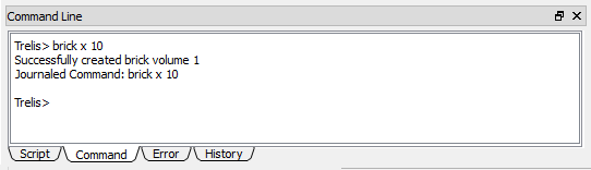
3.2.8.1 Command Window
The command line workspace emulates the environment in the command line version of Cubit. Commands can be entered directly by typing at the cubit> prompt. This window also prints out error messages, informational messages, and journaled commands.
3.2.8.1.1 Entering Commands
To enter commands in the command line workspace, the command window must be active. Activate the command window by clicking anywhere inside the window. Commands are typed in at the cubit> prompt. If you do not remember the specific command sequence you can type help and the name of the command phrase. The input window will show all of the commands that contain that word or phrase. Alternatively, if you know how a command starts, but do not remember all of the options, you can type ? at the end of the command to show all possible command completions. See Command Syntax for an explanation of command syntax rules.
3.2.8.1.2 Repeating Commands
Use the Up and Down arrow keys on the keyboard to recall previously executed commands. Commands can be repeated in other ways as well.
Hitting the enter key while the cursor is on a previous command line will copy that command to the current prompt.
The command window supports copy and paste for repeating commands.
3.2.8.1.3 Focus Follows Cursor
Beginning with version 13.0, Cubit includes a ’focus follows cursor’ option for the command window. The option can be enabled and disabled from the Tools/Options/General options panel. The setting is persistent between sessions and is disabled by default. Please note, the focus follows cursor behavior is available only in the command window. All other windows or widgets require the user to click the mouse in order to grab focus.
3.2.8.2 Error Window
The error window is located in the Command Line Workspace under the Error tab. If there are errors, a warning icon will appear on the tab. The icon will disappear when you open the window to view errors. The error window only displays the error output, which can make it easier to find and read the error output. The command that caused the error will be printed along with the error information. If the command was from a journal file, the file name and number will be printed next to the command.
3.2.8.3 History Window
The history window lists the last 100 commands. The number of commands listed can be configured in the options dialog on the History page. You can re-run the commands in the history window using the context menu. You can also clear the history using the context menu.
3.2.8.4 Script Window
Cubit boasts a robust Python interpreter built right into the graphical user interface. To create a Python script using the Python tab, start typing at the "%>" prompt. At the end of each line, hit Enter to move to the next line . To execute the script, press Enter at a blank line. Scripts may also be written in the Journal File Editor. The Claro Python interpreter works as though you were entering lines from the Python command prompt. This means that a blank line is interpreted as the end of a block. If you want to add whitespace for clarity you have to add a # mark for a comment on any white line that is in a loop or a class. One possible solution to this problem is to create two Python files. The first file can contain the complex set of Python instructions (program.py) including blank lines. The second file will read and execute the first file. An example syntax for the second file is given below.
f = file("program.py") |
commandText = f.read() |
exec(commandText) |
You can then execute the second program within Cubit. The interface between Cubit and python is the "Cubit" object. This object has a method called cmd which takes as an argument a command string. Thus, the following command in the script window:
Cubit.cmd("create brick x 10") |
will create a cube with sides 10 units long. The following script is a simple example that illustrates using loops, strings, and integers in Python.
%>for i in range(4): |
. . x=i*3 |
. . for j in range(4): |
. . . . y=j*3 |
. . . . for k in range(4): |
. . . . . . z=k*3 |
. . . . . . mystr="create vertex x "+str(x)+" y "+str(y)+" z "+str(z) |
. . . . . . Cubit.cmd(mystr) |
This simple script will create a grid of vertices four wide. Scripts can be more advanced, even creating customized windows and toolbars. For a complete list of python/Cubit interface commands see the Appendix.
3.2.8.5 Docking and Undocking the Input Window
The command window can be undocked by clicking and dragging the left edge. If it is floating it can be redocked by double-clicking the solid blue bar. By default, it will always be redocked in the bottom of the application window. To change the size of the floating window, click and drag the edge of the window. To change the height of the docked window, click and drag the top edge or right edge.
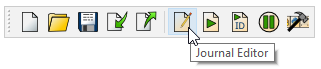
3.2.9 Journal File Editor
The Journal File Editor is a built-in, multi-document text editor that can read, edit, play, and translate Cubit journal files and Python Scripts. To open the journal file editor, select the icon on the File Tools toolbar, or from the Tools Menu.
3.2.9.1 Journal Editor Toolbar
The Journal Editor’s Toolbar provides quick access to several important functions.
New - Creates a new journal file. The new journal file is placed in a new tab.
Open - Used to select a journal file to open.
Save - Saves the current journal file.
Undo - Undo the last text change.
Redo - Redo the last text change, after Undo.
Cut - Standard text cut operation
Copy - Standard text copy operation
Paste - Standard text paste operation
Play Journal File - Plays the entire journal file
Translate to Python - Translates the current Cubit commands in the journal file to Python scripts.
Translate to Cubit - Translates the current Python script in the journal file to Cubit commands.
3.2.9.2 Other Functionality Available in the Journal Editor
The context (’right-click’) menu in the journal editor includes several additional functions, including:
Comment Selected Lines - Highlight any text, select ’comment selected lines’, and the highlighted lines will be commented.
Uncomment Selected Lines - Highlight any text, select ’uncomment selected lines’, and the highlighted lines will be uncommented.
Locate Selected - Highlight an entity in the journal editor and select locate selected. The entity will be identified in the graphics window.
Clear - select this menu item to clear the contents of the journal file.
Find - Selecting ’find’ from the context menu, or from the edit menu, will bring up a dialog enabling the user to find text in the journal file. Options are available to do case-sensitive searches, change search direction, and so forth.
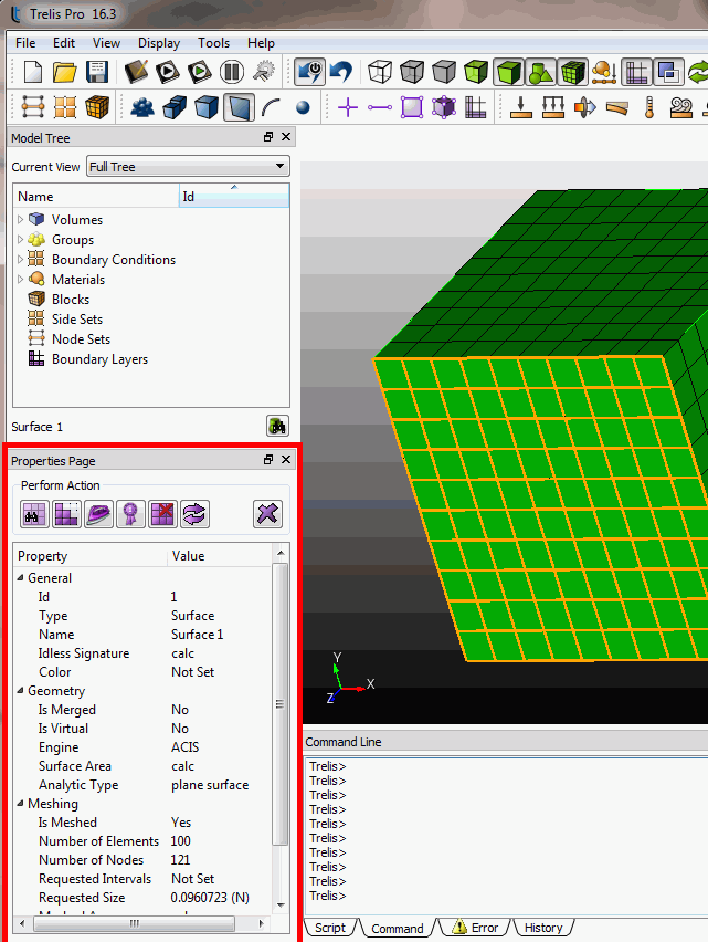
3.2.10 Property Page
The row of buttons on the top of the editor are shortcuts to common commands. These include:
| |
| |
| |
| |
| |
| |
|
3.2.10.1 Editing Entity Attributes from the Property Page
The Property Page provides a convenient way to change attributes on entities. . Some of the fields cannot be changed, some can be edited from an input field, and others are edited by selecting from a list, or by opening the corresponding window from the Control Panel. If multiple entities are selected, the attributes that are similar to both entities will be shown. Changing an attribute from the property page will change that attribute on both entities. If multiple entities are selected the total volume, surface area, and length of all entities will be shown. Below is a summary of properties listed for each attribute type.
3.2.10.1.1 General Attributes
Entity ID - Cubit ID for geometry or boundary condition element
Entity Type - Geometric type such as Volume, Surface, Curve, Vertex
Name - Name by which the entity can be referred to from within Cubit instead of using its ID. The entity name can be edited from this window.
Idless Signature - An idless signature is often useful in journal files. It can be used in place of an explicit ID and will not change from one major version of Cubit to another. A major version change indicates the solid modeling engine has been upgraded.
Color - Opens a dialog box with available colors. A color name can also be input directly into the text field. See Appendix for a list of available colors.
3.2.10.1.2 Geometry Attributes
Is Virtual - Returns "Yes" if this entity is a virtual entity
Location - Returns the location of specified vertex.
Geometry Engine - ACIS or Mesh-Based Geometry
Volume - The volume of the specified body
Surface Area - Surface area of selected surface
Analytic Type - Returns the analytic type of entity (such as cone, sphere, etc)
Length - Length of selected curve
3.2.10.1.3 Meshing Attributes
Number of Elements - Similar to "List Totals" command
Number of Nodes - Number of nodes in the selected entity
Requested Intervals - Number of intervals requested by the user
Requested Size - Requested interval size for element. Clicking on box will open the interval specification panel on the control panel. The interval size can also be entered manually in the text box.
Meshed Volume - The meshed volume may be slightly different than the actual element volume due to the mesh approximation on curved surfaces.
Meshed Area - The meshed area may be slightly different than the actual surface area due to mesh approximation on curved edges.
Length of Meshed Edges - Combined total of mesh edge lengths on curve
Mesh Scheme - The mesh scheme for this entity. This can be changed from the property page by selecting from the drop-down list.
Smooth Scheme - The smooth scheme for this entity. This can be changed from the property page by selecting from the drop-down list.
3.2.10.1.4 Boundary Condition Attributes
ID - Boundary condition ID. This is an arbitrary user-defined ID that is exported with the finite element model. This value can be edited from the property page
Name - A user-defined name that is included in the metadata for that object. This value can be edited from the property page.
Description - A user-defined description that is included in the metadata for that object. This value can be edited from the property page.
Color - Opens a dialog box with available colors. A color name can also be input directly into the text field. See Appendix for a list of available colors.
Element Type - The finite element type for this block, nodeset, or sideset.
Element Count - The total number of elements for this block or sideset
Node Count - Total number of nodes (available for nodesets only)
Attribute Count and Attributes- The attributes represent material specification data that is associated with the element block. These values can be changed in the property page. You can specify up to 10 attributes per block.
3.2.11 Toolbars
The Cubit toolbars provide an effective way for accessing frequently used commands. Below is a brief description of each of the available toolbars. To view a description of the function of each tool, hold the mouse over the tool in the Cubit Application to display tool tips.
3.2.11.1 File
Provides Cubit (*.cub) file operations. This toolbar also includes Journal File operations and tool bar customization operations. From left to right, the buttons are:
New
Open
Save
Import
Export
Journal Editor
Play Journal File
Play ID-Less Journal File
Pause Journal File Playback
Custom Toolbar Editor
3.2.11.2 Display
Controls the display mode, checkpoint undo, zoom, perspective clipping plane, and curve valence display options in the Graphics Window. From left to right, the buttons are:
Enable/disable undo
Undo
Wireframe, True Hidden Line, Hidden Line, Transparent, Shade
Toggle Display of Geometry
Toggle Display of Mesh
Toggle Display of Boundary Conditions
Toggle Display of Graphics Composite
Refresh Display
Zoom In
Zoom Out
Zoom to Fit
Toggle Perspective
Toggle Scale
Toggle Clipping Plane
Clipping Plane Manipulation
Show Curve Valence
Show Overlapping Surfaces
Change Selection Mode to be Enclosed or Extended
Toggle X-Ray Selection Mode
Rubberband Selection Mode